 英语
英语 西班牙语
西班牙语 德语
德语Industry News
Home / News / Industry News / Fire Hose Pressure Explained: Working Pressure, Test Pressure, and Friction Loss


+86-0523-83274900
+86-151 9064 3365
Content
A crew charges a 1-3/4 inch attack line. The pump panel shows 150 psi, the inline gauge near the nozzle shows 95 psi, and the firefighter holding the line still calls the stream soft. Nothing is broken. The 55 psi sitting between those two gauges is friction loss, and it explains most cases where a hose system underperforms even though every part passed inspection.
The short answer first: fire hose pressure is a system number, not a hose number. A line delivers a usable stream only when working pressure, friction loss, nozzle pressure, and the pressure rating of the couplings and adapters all line up. Miss one of them and the weakest component sets the ceiling for the whole assembly.
Five pressure terms come up in almost every conversation about hose performance, and they are routinely used as if they mean the same thing.
| Term | Typical figure | What it means | Where it matters |
|---|---|---|---|
| Working pressure | 150 psi for 1-3/4 inch attack hose, 250 to 300 psi for large diameter supply hose | The pressure the hose is built to hold in continuous service | Sets the ceiling for normal pump discharge settings |
| Service test pressure | Often capped near 300 psi for 1-1/2 and 1-3/4 inch hose | Hydrostatic pressure applied during periodic testing | Decides whether a length stays in service or is retired |
| Burst pressure | Roughly three times working pressure | The destructive limit before the jacket fails | A safety margin, never an operating target |
| Residual pressure | Read at the hydrant or pump while water is flowing | Supply pressure remaining after the flow demand is met | Shows whether the water supply can support the line |
| Nozzle pressure | About 100 psi for combination nozzles, about 50 psi for smooth bore | Pressure required at the nozzle inlet | Controls stream reach, shape, and droplet size |
Working pressure is a continuous duty rating. Test pressure is an occasional duty rating applied for a short period under controlled conditions. They are not interchangeable, and treating them as a single number is where a lot of confusion starts.
Modern hose is often rated between 300 and 400 psi at the jacket, while normal operating pressure on an attack line sits around 100 to 150 psi at the nozzle. That gap is deliberate. It gives the jacket and the hardware room to absorb surge, water hammer, and the occasional kink without a failure.
Service testing pushes a length far above that normal band. For 1-1/2 inch and 1-3/4 inch hose, the test pressure is often capped near 300 psi, largely because kinks that go unnoticed at lower pressure become genuinely dangerous above that point. The consequence is easy to overlook: a length rated at 150 psi working pressure gets pressurized to roughly twice that in the test bay, and everything latched, threaded, or clamped onto it has to survive the same pressure. A coupling with a lower rating than the jacket turns a 300 psi assembly into a 150 psi assembly, no matter what the hose label says.
Friction loss is the pressure consumed simply by pushing water through the hose. It is the single largest reason a pump panel reading does not match what the nozzle actually receives.
The field formula is FL = C x Q squared x L, where Q is flow in hundreds of gallons per minute and L is length in hundreds of feet. The C value reflects diameter and lining: roughly 150 for 1 inch hose, about 15.5 for 1-3/4 inch, and near 2 for 2-1/2 inch.
A worked example makes the arithmetic concrete. Take 200 feet of 1-3/4 inch hose flowing 150 gpm into a combination nozzle that needs 100 psi at the inlet. Friction loss is 15.5 x 1.5 x 1.5 x 2, or about 70 psi. Add the nozzle requirement plus a small allowance for appliance losses, and the pump needs to produce roughly 175 to 180 psi to keep 100 psi at the tip. Run the same 150 gpm through 2-1/2 inch hose and friction loss drops to about 9 psi, which is exactly why supply lines are sized generously and attack lines are kept short.
Calculations are estimates, not measurements. Flow testing is what confirms how the hose, pump, appliances, and nozzle work together as one system, and a calibrated pitot gauge or flow meter is the only way to know whether the numbers hold up on your apparatus.
Couplings contribute friction loss and also set the pressure ceiling of the assembly, yet selection sheets often focus on the hose alone. Five details decide how a coupling behaves under pressure.
Couplings are also where field mistakes surface fastest. A gasket seated crooked, a latch that does not fully engage, or a threaded joint left hand tight will hold at low pressure and leak above 100 psi. Reviewing how a fire hose joint should be connected correctly is worth ten minutes before every season, not just after a failure. Where equipment from different standards has to meet, cross-standard adapters handle the transition, but each adapter introduces another bore change and another pressure rating to check.
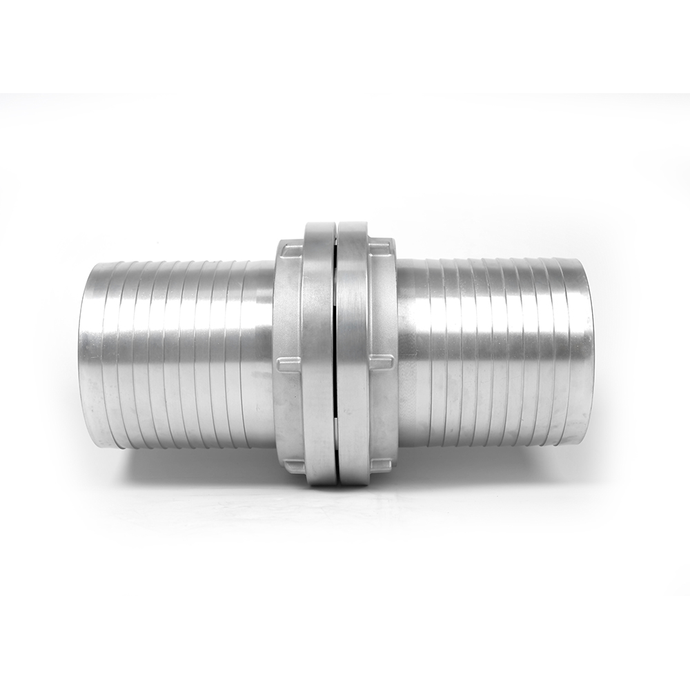 Large Storz Fire Hose CouplingLarge Storz-style coupling with serrated or ribbed tail ends and DIN sizes from 25 to 300 mm, useful for checking hose joints before pressure testing.View Product →
 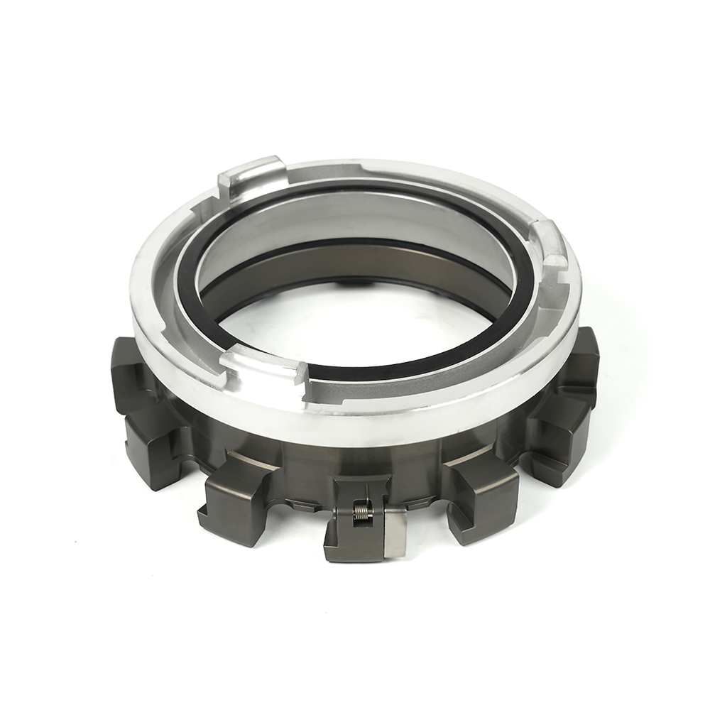 Multi-Tooth Storz Adapter Coupling RangeAdapter couplings connect different standards and fitting types, with customizable configurations and DIN combinations from 150/200 to 300/400 for cross-standard connections.View Product →
Nozzle pressure is the target the whole system is tuned around. Combination nozzles typically want about 100 psi at the inlet to produce a workable fog pattern and reach. Smooth bore nozzles run lower, usually around 50 psi, and are far less sensitive to small errors in pump setting.
Raising nozzle pressure also raises nozzle reaction, and that number is not theoretical. Reaction force in pounds is roughly 0.0505 x flow in gpm x the square root of nozzle pressure. At 150 gpm and 100 psi, that works out to about 76 pounds of push against the crew. At 200 gpm the same calculation gives over 100 pounds, which is well past what one person can hold on a ladder or in a stairwell.
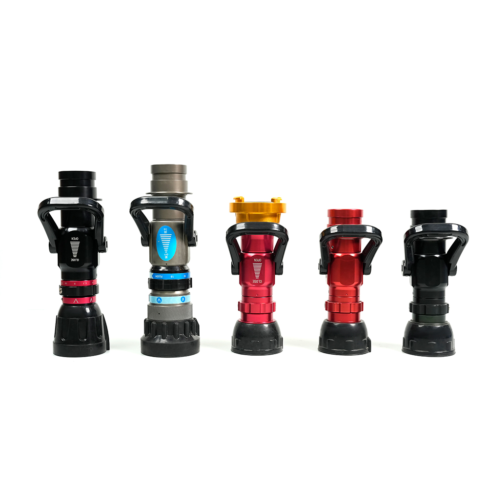 Adjustable Storz Fire Nozzle with Multiple Spray PatternsAdjustable fire nozzle with straight stream, fog, fan spray, and water curtain modes, plus quick on/off valve control and lightweight recoil-free handling.View Product →
An adjustable nozzle lets the operator trade stream shape against reach without changing the pump setting, but the pressure target at the inlet stays the same. If the gauge at the nozzle reads low, fix the supply side first rather than opening the pattern further.
A distributor splits one incoming line into two, three, or four outgoing lines, and each outlet carries its own friction loss and its own nozzle requirement. A two-way unit feeding two 1-3/4 inch lines at 150 gpm each demands roughly twice the water of a single line, and the supply line behind it has to be sized for that total, not for one branch.
Locking versions matter at higher pressures because latch security, not flow capacity, is usually what fails first when a charged line is dragged across gravel or pulled around a corner.
Fire hose pressure is a chain, and the chain is only as strong as the lowest rating in it. Get the working pressure, friction loss, nozzle target, and hardware ratings consistent with one another, verify the numbers with a flow test rather than a calculation, and most of the soft-stream complaints disappear before anyone reaches the nozzle.
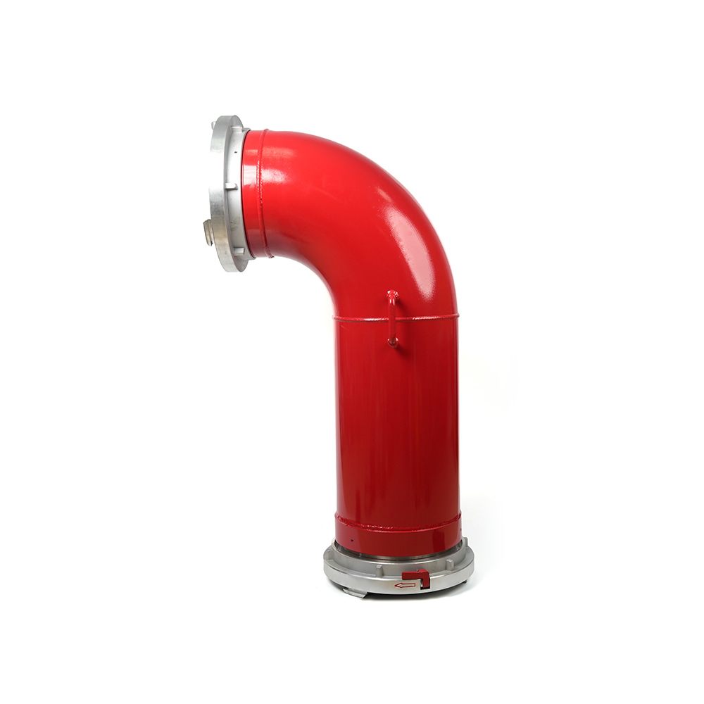 Grooved Fire Elbow-Storz
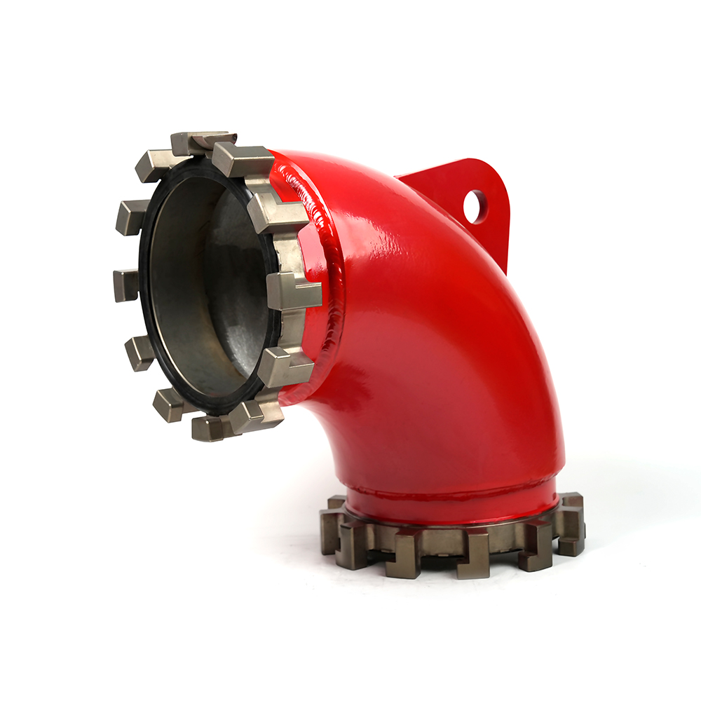 Grooved Fire Elbow-Multi-tooth
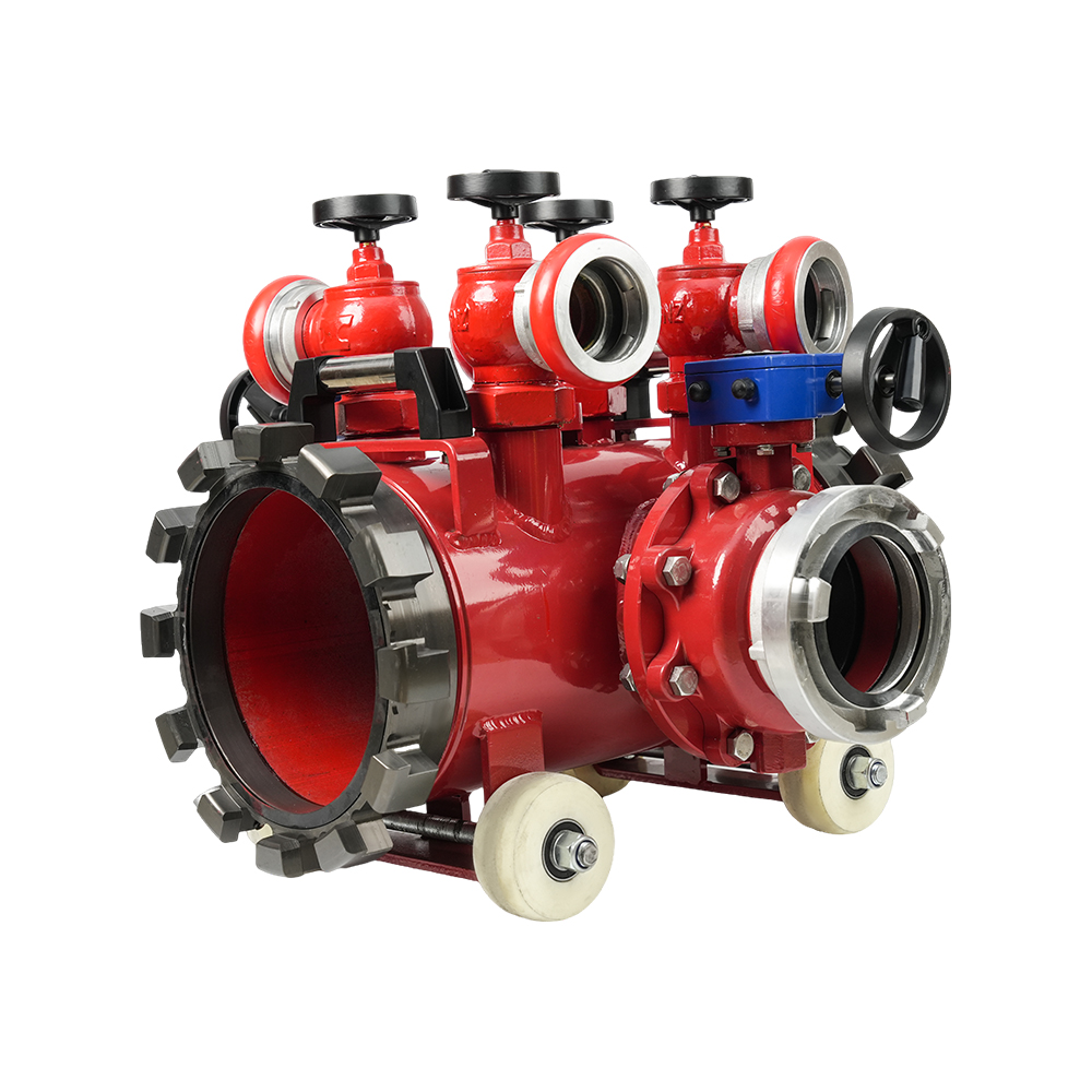 Multi-functional Fire Hose Distributor
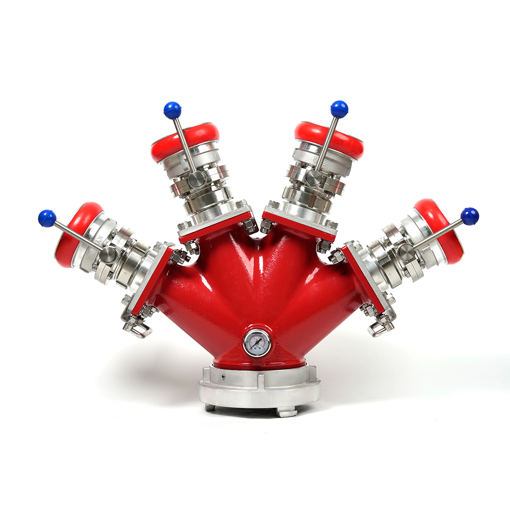 Locking Four-Way Fire Hose Distributor
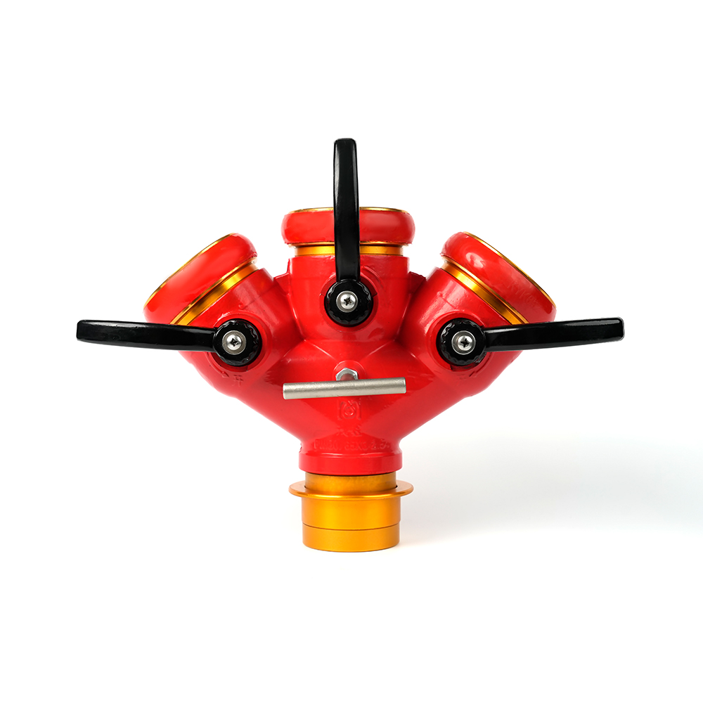 Locking Three-Way Fire Hose Distributor
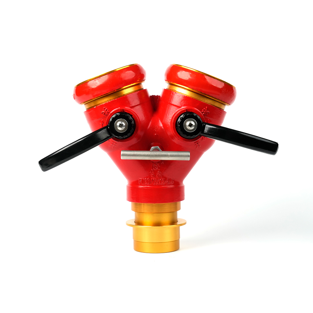 Locking Two-Way Fire Hose Distributor
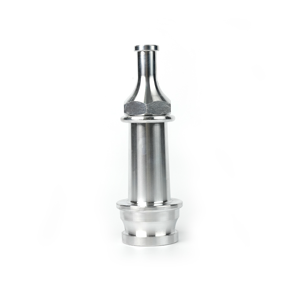 Straight Stream Nozzle
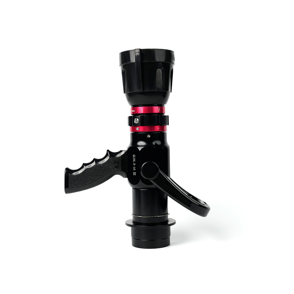 Adjustable nozzle-machino
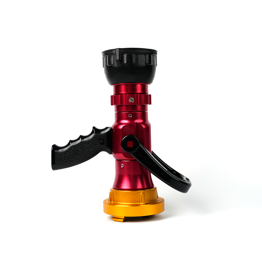 Adjustable nozzle-storz
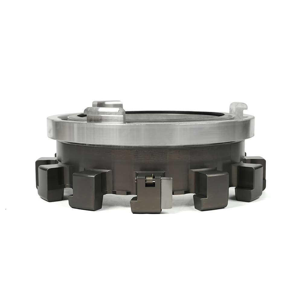 Storz Adapter Couplings - Multi-Tooth
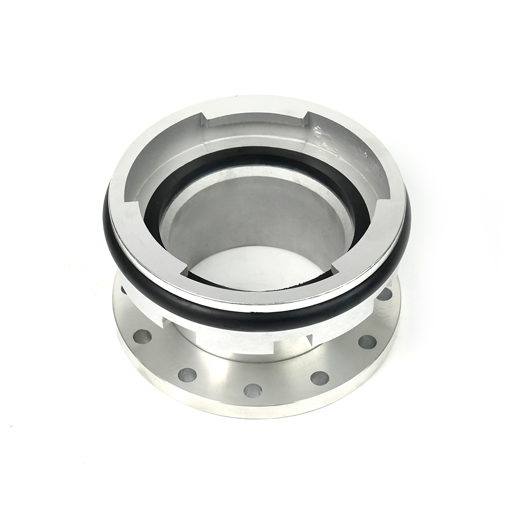 Machino Adapter Couplings – Flanged
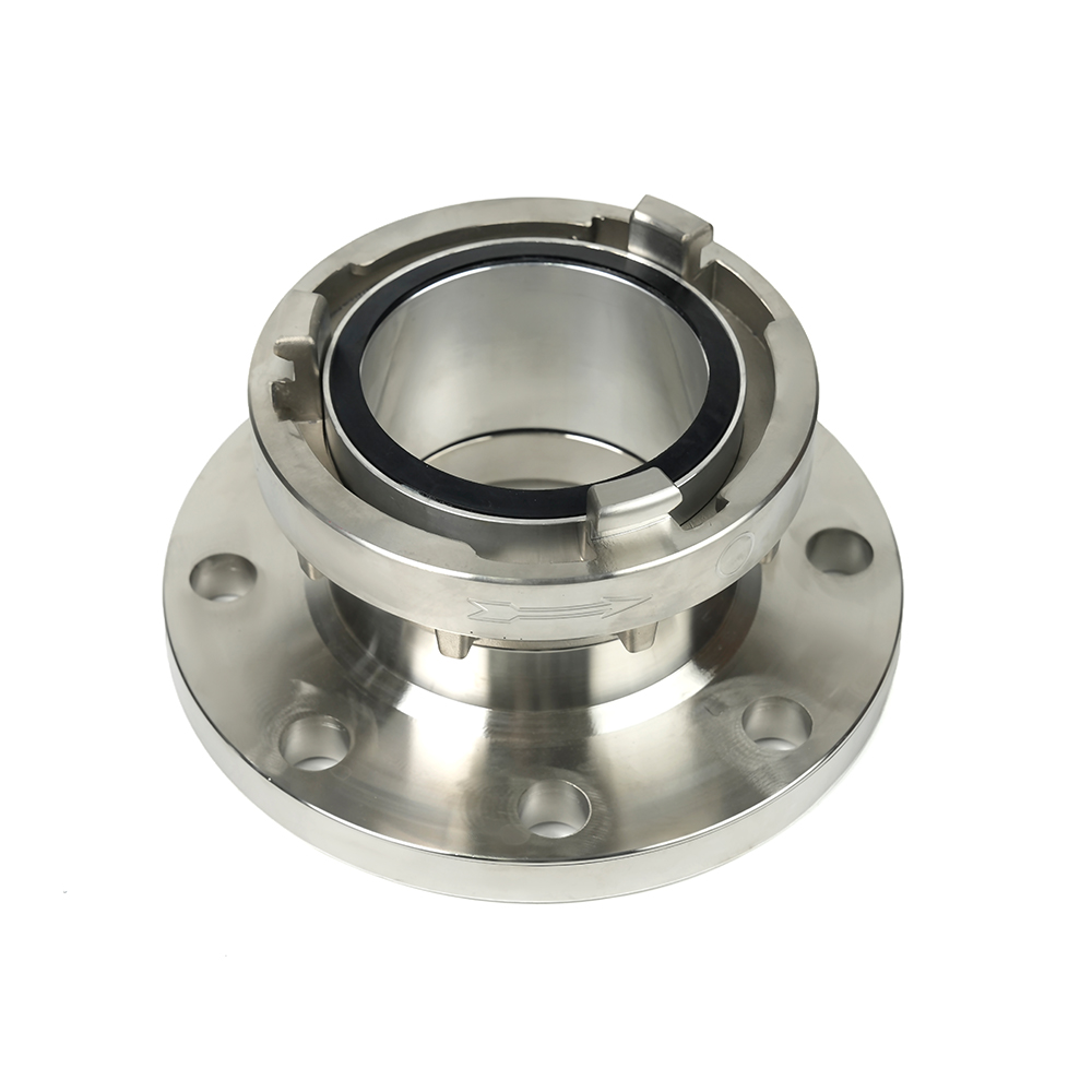 Storz Adapter Couplings – Flanged

 Contact Number
+86-0523-83274900
+86-151 9064 3365
 Let our team offer you customs solutions.
 Company Address
West side of Hongxing Middle Road, Lincheng Street, Development Zone, Xinghua City, Jiangsu Province, China
Copyright @Jiangsu Jinding Fire Protection Technology Co., Ltd. All rights reserved Fire Protection Equipments Manufacturers
