 英语
英语 西班牙语
西班牙语 德语
德语Industry News
Home / News / Industry News / Fire Hose Friction Loss Formula: Coefficients, Examples and Pump Pressure


+86-0523-83274900
+86-151 9064 3365
Content
A 200-foot attack line of 1.75-inch hose flowing 150 gallons per minute burns about 70 psi before the water ever reaches the nozzle. Pump operators who skip that number usually find out through a short, weak stream and a lot of guessing at the throttle. The tool that predicts it is one multiplication: FL = C x Q^2 x L, where FL is friction loss in psi, C is a coefficient set by hose diameter and lining, Q is flow in hundreds of gallons per minute, and L is hose length in hundreds of feet.
What follows is how the formula behaves unit by unit, which coefficients apply to common hose sizes, how the result becomes a pump discharge pressure, and where adapters, reducers and distributors quietly change the answer.
Friction loss is pressure spent on turbulence and drag as water slides along the hose lining. It rises in a straight line with length and with the square of flow, which is why a modest increase in gallons per minute can consume a large share of the pump output.
Worked example: 200 feet of 1.75-inch hose at 150 gpm. Q is 1.5, so Q squared is 2.25, and L is 2. FL = 15.5 x 2.25 x 2, which comes to 69.75 psi, or roughly 70 psi.
Two behaviors fall straight out of that arithmetic. Double the hose length and the loss doubles. Double the flow and the loss quadruples, because the flow term is squared.
Published C values come from flow tests on specific hose constructions. The figures below are the widely used planning values for lined fire hose, and they work well as a starting point for layout calculations.
| Hose size | C coefficient | Loss at 100 gpm | Loss at 200 gpm |
|---|---|---|---|
| 1 1/2 inch | 24 | 24 psi | 96 psi |
| 1 3/4 inch | 15.5 | 15.5 psi | 62 psi |
| 2 inch | 8 | 8 psi | 32 psi |
| 2 1/2 inch | 2 | 2 psi | 8 psi |
| 3 inch | 0.8 | 0.8 psi | 3.2 psi |
| 4 inch | 0.2 | 0.2 psi | 0.8 psi |
| 5 inch | 0.08 | 0.08 psi | 0.32 psi |
The table explains why large diameter hose dominates supply work. Moving 200 gpm through 1.75-inch hose costs about 62 psi per 100 feet. Moving that same flow through 4-inch hose costs less than 1 psi.
The pump panel figure follows a simple sum: discharge pressure equals nozzle pressure plus friction loss plus elevation gain plus appliance loss.
Example one: 200 feet of 1.75-inch hose at 150 gpm with a fog nozzle at 100 psi on level ground gives 100 + 70, or 170 psi at the panel.
Example two: the same flow through 200 feet of 2.5-inch hose. FL = 2 x 2.25 x 2 = 9 psi, so the panel figure is 100 + 9, or 109 psi.
Same stream, 61 psi less at the pump. The difference is not the nozzle and not the pump; it is the bore of the hose carrying the water.
Friction loss lives inside the hose, but it is controlled at the connections. Any component that narrows the waterway adds a local pressure drop, and any component that reduces the effective diameter across a hose section changes the C value used for that section.
A step down from 1 3/4 inch to 1 1/2 inch raises the coefficient from 15.5 to 24, roughly 55 percent more loss at the same flow. A reducing adapter at the pump panel outlet or at the nozzle inlet is therefore not pressure-neutral hardware. It is a deliberate trade of pressure for interface compatibility.
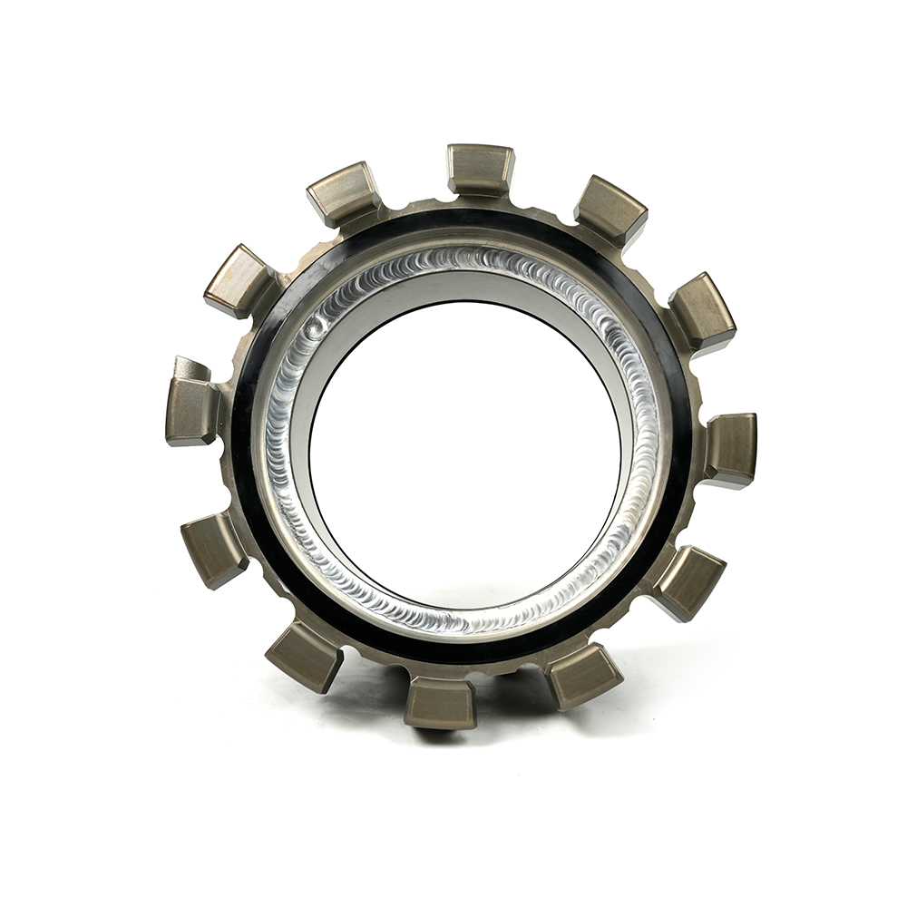 Multi-Tooth Reducer for Different-Size Fire Hose ConnectionsConnects different-size multi-tooth fire hoses or equipment; a practical choice when hose and equipment interfaces require a size change, with customizable dimensions.View Product →
On the supply side, the arithmetic rewards bore. A large diameter coupling that keeps the full waterway open through the connection preserves the low C value of the hose behind it, which is exactly what long lays and high flows demand.
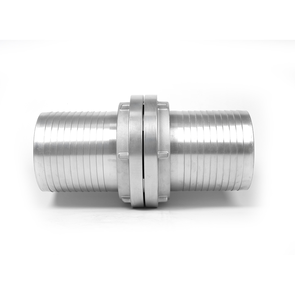 Large Storz Fire Hose Coupling for Supply ConnectionsLarge-size Storz fire hose coupling with serrated or ribbed tail ends and sizes up to 300 mm for large-diameter supply connections.View Product →
A two-way distributor does not halve friction loss. Upstream of the split, the supply line carries the sum of both flows, and that total is what goes into the formula. Two 150 gpm attack lines fed from one supply line mean 300 gpm, or a Q of 3, in the supply calculation. For 200 feet of 2.5-inch supply hose, the loss is 2 x 9 x 2, or 36 psi, before either attack line is even considered. Add the appliance loss of the distributor and the panel pressure climbs further.
Nozzle pressure is not friction loss, but the two compete for the same pump output. A nozzle rated at 100 psi needs 100 psi at its inlet, and every psi lost in the hose comes out of stream reach and penetration.
Adjustable nozzles normally run at 100 psi and shift between straight stream, narrow fog and wide fog patterns. Each pattern changes effective flow and therefore the friction loss upstream, which is why a pump setting copied from a straight stream drill can disappoint once the pattern is opened up. For background on how those patterns behave, see the spray modes of the adjustable nozzle.
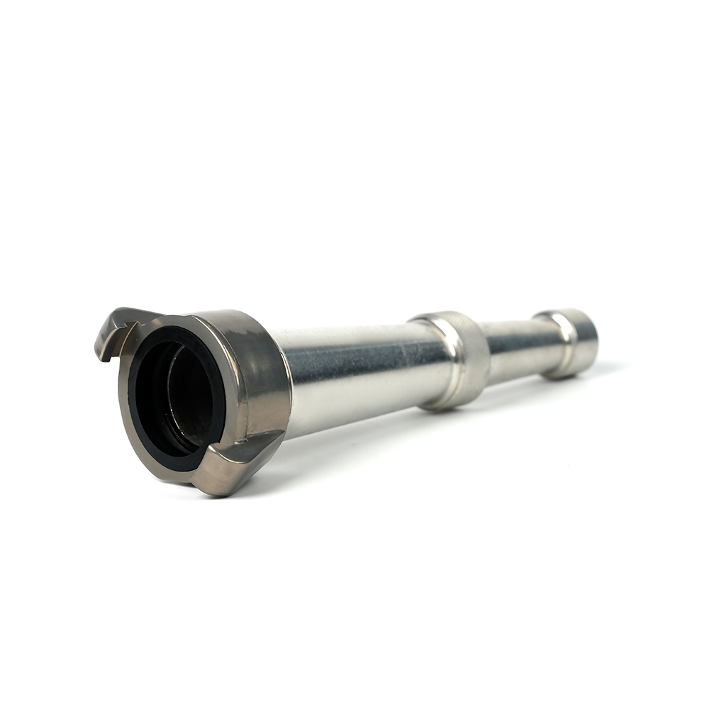 Straight Stream Nozzle for Long-Distance Fire SuppressionDelivers a solid, dense columnar jet for long-distance suppression; some models include a ball valve for quick flow control and help prevent pressure surges.View Product →
Straight stream and smooth bore devices are less sensitive to this effect, because their flow is set by nozzle diameter and inlet pressure rather than by an adjustable pattern.
Pump operators rarely multiply in their heads at three in the morning. A useful shortcut for 1.75-inch hose is worth memorizing: about 15 psi per 100 feet at 100 gpm, 35 psi at 150 gpm and 62 psi at 200 gpm. For 2.5-inch hose, the same flows cost roughly 2, 4.5 and 8 psi per 100 feet.
Verification is straightforward on a training ground. Set a known flow with an inline flowmeter, read pressure at the pump and at the nozzle inlet, and subtract. After adjusting for elevation, the difference is the real friction loss of that hose at that flow. Comparing it against the calculated value shows whether the published coefficient still fits the hose in service.
Running that check once a year catches lining wear, changed coupled lengths and any restriction introduced by a coupling or adapter that was swapped in without review.
The formula rewards three specification habits. Keep the working bore as large as the operation allows, avoid unnecessary reductions between the pump and the nozzle, and confirm that every coupling and adapter matches both the hose and the thread or locking standard in use.
That last point matters most on international projects, where Storz, Machino, NH and other patterns appear side by side. An adapter that crosses standards is only useful if its waterway matches the hose it joins, because a restricted bore behaves exactly like a smaller hose in the calculation.
If the pressure budget has to hold up in the field, it is worth confirming dimensions and flow requirements before the hardware is ordered. Share the operating conditions with the engineering team and check the numbers against the actual components rather than against a generic table. The formula stays the same; only the inputs change.
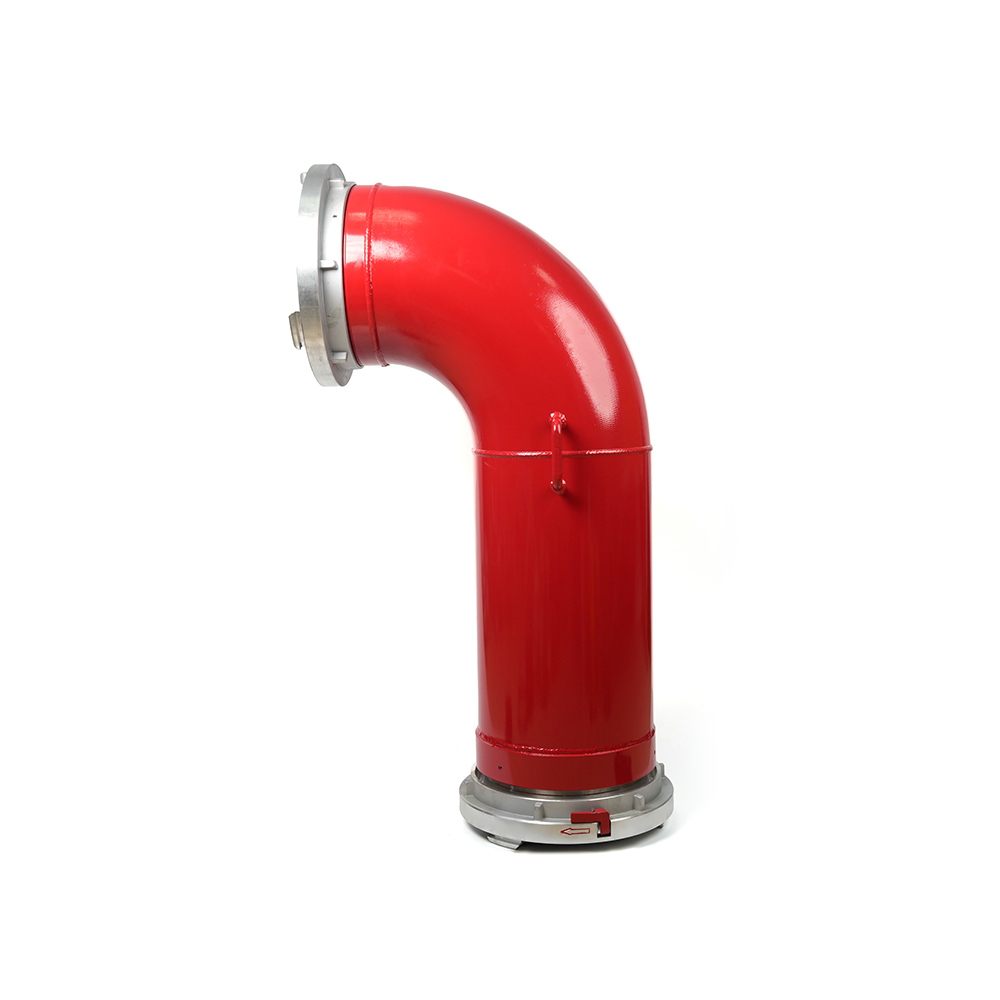 Grooved Fire Elbow-Storz
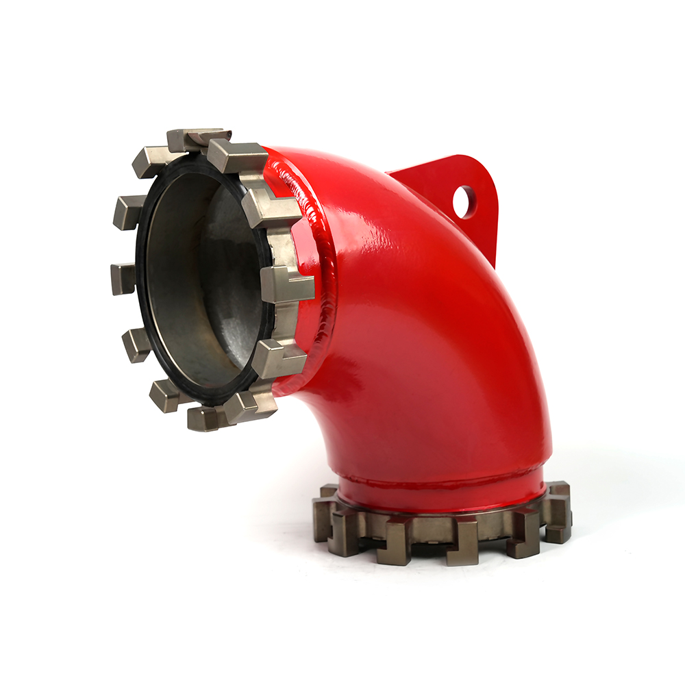 Grooved Fire Elbow-Multi-tooth
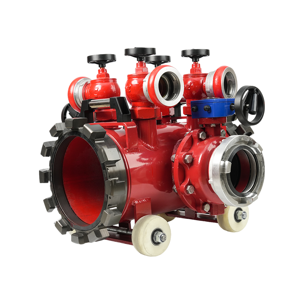 Multi-functional Fire Hose Distributor
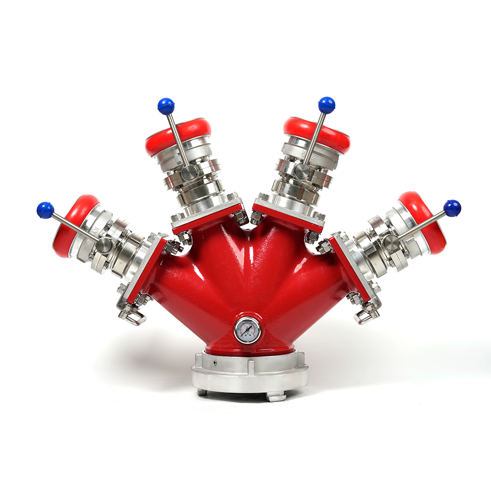 Locking Four-Way Fire Hose Distributor
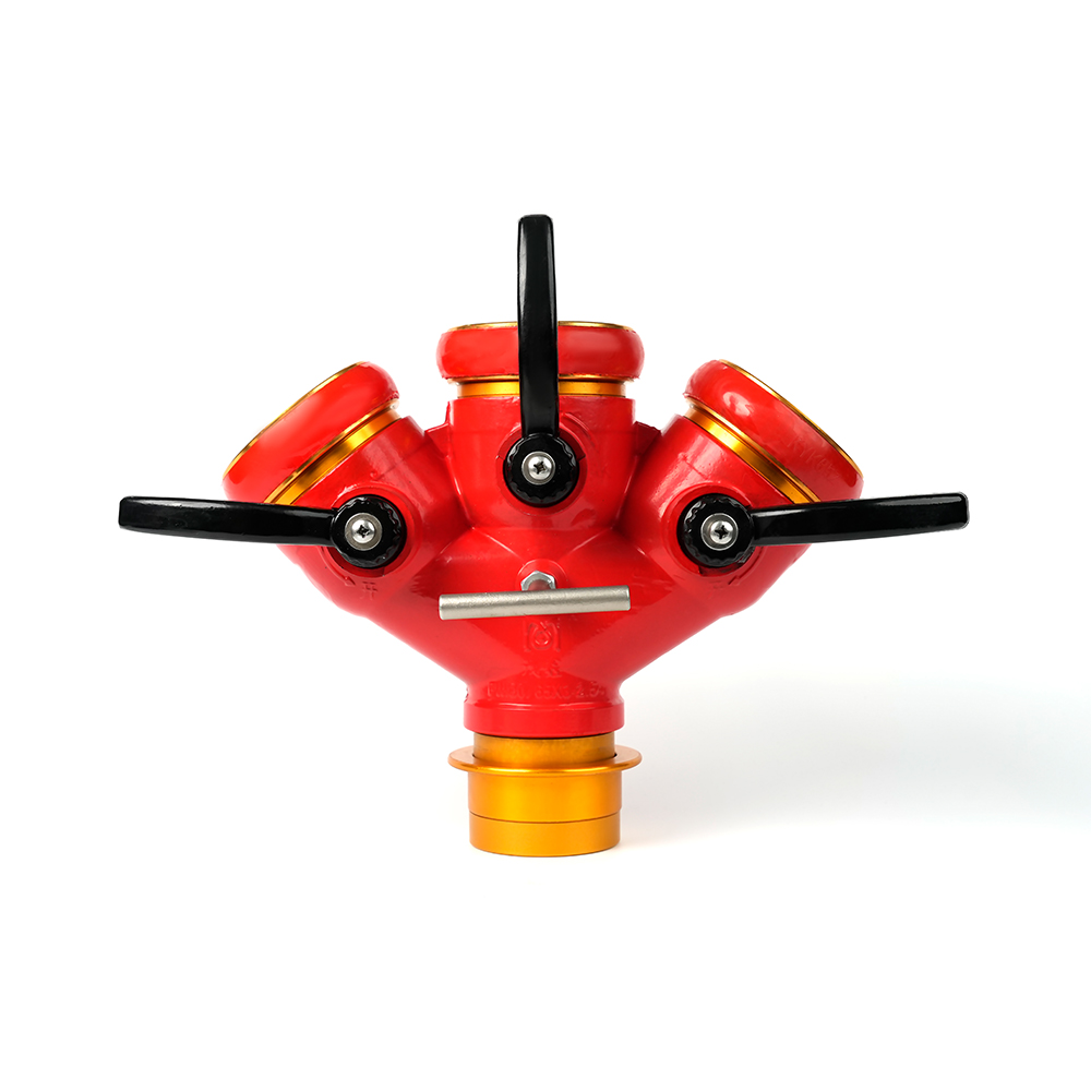 Locking Three-Way Fire Hose Distributor
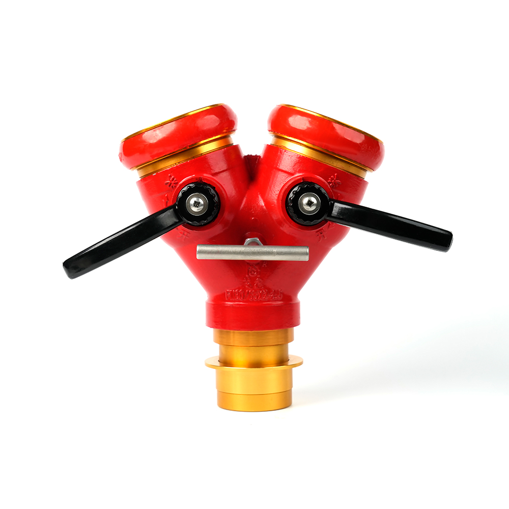 Locking Two-Way Fire Hose Distributor
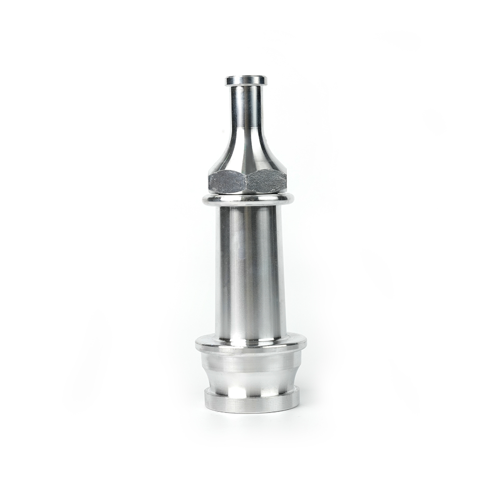 Straight Stream Nozzle
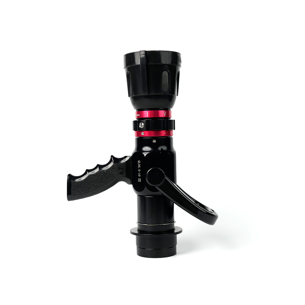 Adjustable nozzle-machino
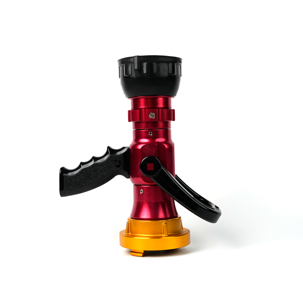 Adjustable nozzle-storz
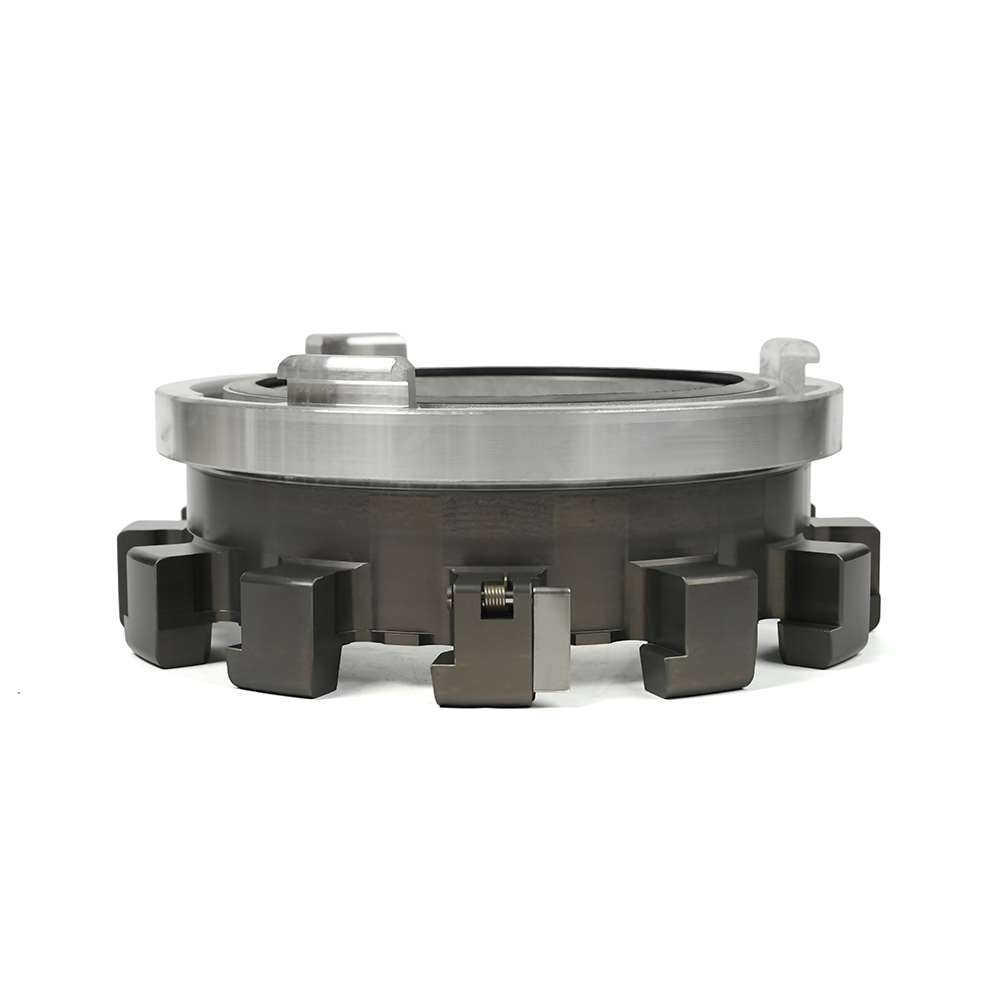 Storz Adapter Couplings - Multi-Tooth
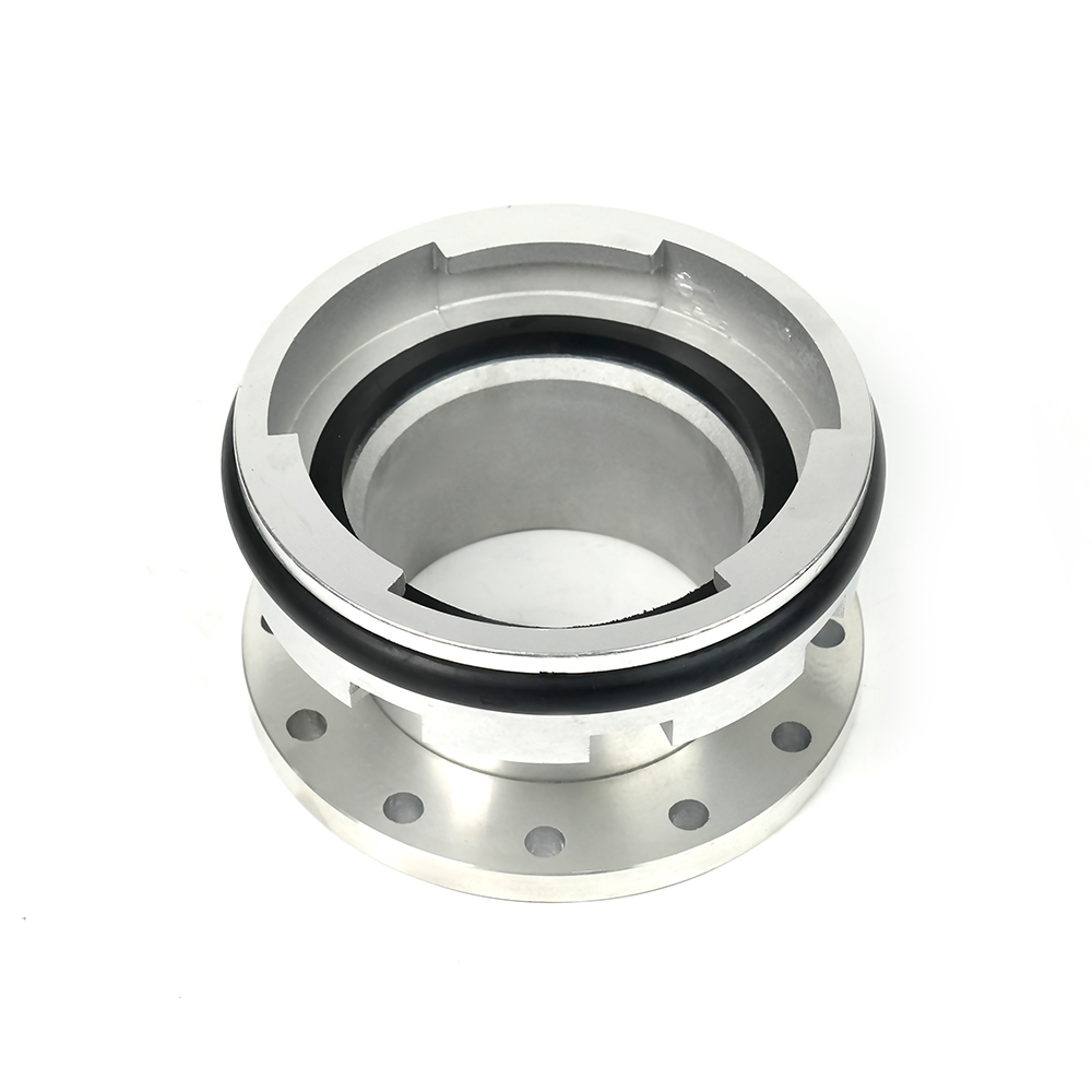 Machino Adapter Couplings – Flanged
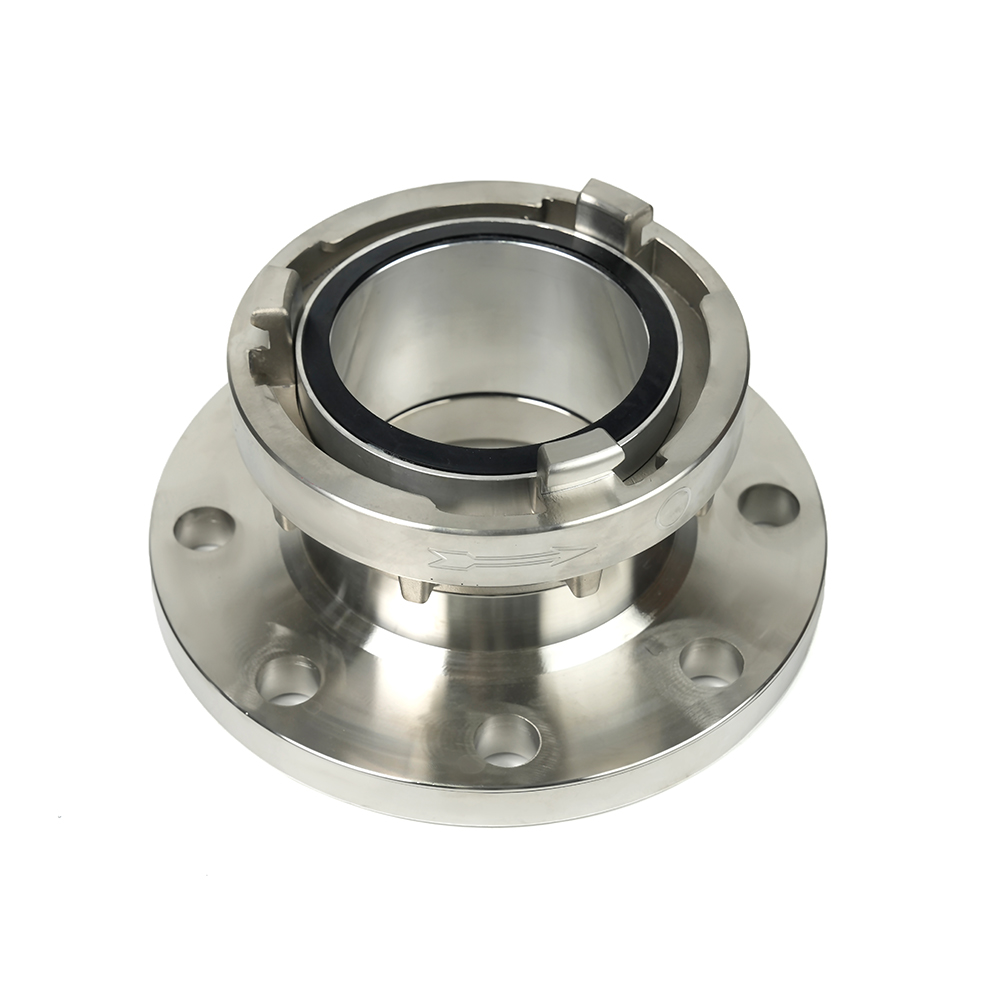 Storz Adapter Couplings – Flanged

 Contact Number
+86-0523-83274900
+86-151 9064 3365
 Let our team offer you customs solutions.
 Company Address
West side of Hongxing Middle Road, Lincheng Street, Development Zone, Xinghua City, Jiangsu Province, China
Copyright @Jiangsu Jinding Fire Protection Technology Co., Ltd. All rights reserved Fire Protection Equipments Manufacturers
