 英语
英语 西班牙语
西班牙语 德语
德语Industry News

GET IN TOUCH
+86-0523-83274900
+86-151 9064 3365
Content
Installing a multi-tooth coupling correctly involves five core steps: verifying shaft and bore dimensions, cleaning and preparing the mating surfaces, mounting the hubs with proper alignment, engaging the gear teeth with correct lubrication, and final torque-checking and run verification. The single most important factor in a successful installation is shaft alignment — multi-tooth couplings are designed to accommodate a degree of misalignment in operation, but exceeding the rated angular or parallel misalignment during installation accelerates tooth wear dramatically and can lead to premature failure. This guide walks through the complete installation process in practical detail, with the tolerances and torque values that determine whether a coupling performs reliably for years or fails within months.
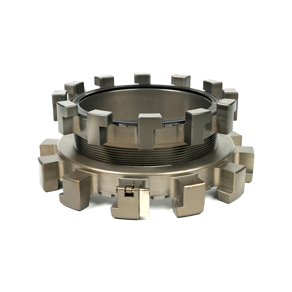
A multi-tooth coupling (also called a gear coupling) transmits torque between two shafts through meshing crowned gear teeth on a hub that engages with internal straight teeth on a sleeve. The crowned tooth profile allows the coupling to accommodate angular misalignment while teeth remain in full contact across their face width, distributing load evenly even when the connected shafts are not perfectly aligned.
Most industrial Multi-Tooth Couplings consist of two hubs keyed or fitted to the driving and driven shafts, an external sleeve (or two half-sleeves bolted together) that meshes with both hubs, and seals to retain lubricant within the tooth mesh. Understanding this construction is essential before installation, because the alignment tolerance and lubrication requirements both stem directly from how the gear teeth interact under load.
Standard multi-tooth couplings typically accommodate angular misalignment of 0.5 to 1.5 degrees per mesh and parallel offset misalignment proportional to coupling size, generally in the range of 0.1 to 0.5 mm depending on the coupling's pitch diameter (Source: AGMA 9004-A99, Flexible Couplings — Mass Elastic Properties and Other Characteristics). While this tolerance provides genuine operational flexibility, installation should always target alignment as close to zero as practically achievable — operating consistently at the maximum rated misalignment significantly shortens coupling service life compared to operating near the ideal aligned condition.
Gathering the correct tools before beginning prevents delays and reduces the risk of installation errors that are difficult to correct once the equipment is running.
Before any mounting work begins, confirm that the shaft diameter and the coupling hub bore are dimensionally compatible according to the specified fit class. Most multi-tooth couplings use either a clearance fit with a key, or an interference (shrink) fit for high-torque or reversing-load applications.
Measure the actual shaft diameter with a micrometer at multiple points along the hub engagement length and compare against the coupling manufacturer's specified bore tolerance. A typical clearance fit for a keyed connection might specify a bore tolerance of H7 against a shaft tolerance of k6, per ISO 286 fit and tolerance standards — producing a light interference to transition fit that keeps the hub centered while still permitting assembly by hand or with light force.
Inspect the keyway on both the shaft and the hub bore for correct width, depth, and squareness. A keyway that is undersized in width will prevent the key from seating fully, creating a rocking condition under load; an oversized keyway reduces the load-bearing contact area of the key and can lead to key shear under heavy torque cycling.
Inspect the shaft end, keyway edges, and hub bore for burrs, nicks, or corrosion. Even small burrs at the shaft end or keyway edge can prevent the hub from seating to its full depth, creating a gap that throws off all subsequent alignment measurements. Deburr with a fine file or stone, then clean thoroughly with solvent and a lint-free cloth before proceeding.
Hub mounting method depends on the fit type specified for the application — clearance fit hubs can typically be installed cold with hand tools, while interference fit hubs require controlled heating to expand the bore sufficiently for assembly without damaging the shaft or hub.
For high-torque applications where an interference fit is specified, the hub bore must be expanded thermally before it can be slid onto the shaft. Heating to 80 to 120 degrees Celsius above ambient is typical for moderate interference fits, though the exact temperature must be calculated from the specific interference amount and hub material — never exceed 400 degrees Celsius for steel hubs, as this risks altering the material's heat treatment and mechanical properties (Source: SKF, Mounting and Dismounting of Rolling Bearings, general principles applicable to interference-fit machine elements).
Shaft alignment is the single most critical step in multi-tooth coupling installation. While these couplings tolerate some misalignment during operation, the alignment achieved at installation directly determines the coupling's service life and the vibration levels the connected machinery will experience.
It is a common misconception that because a multi-tooth coupling can accommodate 1 degree of angular misalignment, it is acceptable to install it at close to that limit. In practice, operating near the maximum rated misalignment concentrates tooth contact stress on one edge of the tooth face rather than distributing it evenly, accelerating wear at a rate disproportionate to the misalignment angle. Field reliability data compiled by coupling manufacturers and reported in AGMA technical literature indicates that coupling life can be reduced by 50% or more when operating misalignment exceeds approximately one-third of the rated maximum on a sustained basis (Source: AGMA 9004-A99, Flexible Couplings — Mass Elastic Properties and Other Characteristics).
As a practical installation target rather than the maximum rated tolerance, aim for the following alignment values, which represent good general practice for industrial multi-tooth coupling installations at moderate operating speeds:
| Alignment Parameter | Good Installation Target | Acceptable Maximum (Reference) |
|---|---|---|
| Angular misalignment | Less than 0.25 degrees | 0.5 to 1.0 degrees (size dependent) |
| Parallel offset | Less than 0.05 mm | 0.1 to 0.3 mm (size dependent) |
| Axial gap (sleeve to hub) | As specified on drawing, plus or minus 0.5 mm | Within manufacturer specified range |
| Reference values; always confirm against the specific coupling manufacturer's installation manual, as exact tolerances vary by coupling size and design | ||
The reverse-indicator method is widely used for coupling alignment and provides reliable results without requiring the equipment to be perfectly accessible from a single side:
For critical applications, high-speed equipment, or where maximum accuracy and efficiency are required, laser shaft alignment systems offer significant advantages over dial indicators: they eliminate sag and bracket deflection errors common to dial indicator setups, provide real-time digital readouts that guide the technician directly to the required shim and lateral adjustments, and typically reduce alignment time by 50% or more compared to manual dial indicator methods. For multi-tooth couplings operating above 1,500 RPM or in critical process applications, laser alignment is strongly recommended over manual methods.
Once shaft alignment is within target tolerance, the coupling sleeve can be installed over the meshing hubs and the lubrication system completed. Correct lubrication is just as important to coupling life as correct alignment — gear teeth operating under boundary or mixed lubrication conditions wear at dramatically accelerated rates.
Position the sleeve (or sleeve halves, for split-sleeve designs) over the aligned hubs, ensuring the internal teeth engage smoothly with the external crowned teeth on both hubs. If the sleeve does not slide on smoothly, do not force it — this typically indicates a remaining alignment issue or a burr on the tooth surfaces that should be addressed before proceeding. For split-sleeve designs, fit and torque the sleeve bolts in the cross-pattern sequence specified by the manufacturer to ensure even clamping force around the joint.
Multi-tooth couplings are lubricated by one of two methods: continuous oil bath (or oil mist) lubrication, common in continuously running industrial drives, or periodic grease lubrication, common in couplings with removable seals that are re-greased at scheduled maintenance intervals.
| Lubrication Type | Typical Re-lubrication Interval | Best Suited For |
|---|---|---|
| Continuous oil bath | Oil change every 6 to 12 months | Continuously running industrial drives, high speed |
| Grease pack (sealed) | Every 3,000 to 8,000 operating hours, or per manufacturer schedule | General industrial drives, moderate speed and load |
| Grease pack (frequent misalignment) | Every 1,000 to 2,000 operating hours | Applications with higher continuous misalignment |
| Indicative re-lubrication intervals; always follow the specific coupling manufacturer's recommended schedule, which accounts for the exact coupling design, speed rating, and lubricant specification | ||
Use only the lubricant type and grade specified by the coupling manufacturer. Multi-tooth coupling grease typically uses a lithium or lithium-complex base with extreme pressure (EP) additives formulated specifically to withstand the high contact pressures and sliding action present at the crowned tooth interface — standard bearing or general-purpose grease is not an adequate substitute and will lead to accelerated tooth wear and premature coupling failure.
Fill grease-lubricated couplings to the level specified by the manufacturer, typically through a fill port with the coupling rotated to specific positions to ensure the lubricant reaches all tooth surfaces. Avoid overfilling, which can cause excessive internal pressure and seal damage during thermal expansion at operating temperature.
Sleeve bolts, set screws, and any retaining hardware must be torqued to the manufacturer's specified values, not simply tightened by feel. Under-torqued fasteners can loosen under vibration and cyclic loading, while over-torqued fasteners can yield or strip threads, both of which compromise the coupling's integrity. As a general reference, metric Grade 8.8 bolts in the size range commonly used on industrial coupling sleeves (M10 to M20) are typically torqued in the range of 45 to 280 Nm depending on exact bolt size and the specific manufacturer's specification — always confirm the exact value from the coupling's installation documentation rather than relying on generic bolt torque tables, as coupling manufacturers often specify values calculated specifically for their joint design.
Use a calibrated torque wrench and tighten fasteners in the sequence specified by the manufacturer — typically a cross or star pattern for multi-bolt sleeve joints — applying torque in two or three incremental passes rather than fully torquing each bolt sequentially, which helps ensure even clamping force distribution around the joint.
Before the coupling is operated, install the protective guard required by workplace safety regulations in virtually all jurisdictions for any rotating shaft coupling. The guard must fully enclose the rotating coupling components while allowing for any thermal growth or vibration that may occur during operation, and should include access provisions for routine lubrication checks without requiring full guard removal.
After installation is complete, conduct an initial run-in period with close monitoring:
| Mistake | Consequence | Prevention |
|---|---|---|
| Installing without checking shaft and bore tolerance | Loose fit causes fretting and hub movement under load | Measure shaft diameter and bore before mounting; confirm fit class |
| Aligning to the maximum rated misalignment | Accelerated tooth wear; significantly reduced coupling life | Target alignment well within rated tolerance, ideally less than one-third of maximum |
| Using general-purpose grease instead of coupling-specific lubricant | Inadequate film strength at tooth contact; premature wear | Use manufacturer-specified EP coupling grease or oil only |
| Skipping the run-in torque re-check | Loosened fasteners lead to coupling slip or sleeve movement | Re-torque all fasteners after the initial run-in period |
| Overheating hubs during interference-fit installation | Altered material properties; reduced hub strength | Monitor temperature precisely; stay within manufacturer's specified heating range |
| Operating without a protective guard | Serious safety hazard to personnel near rotating equipment | Always install and secure the guard before energizing the drive |
| Common field installation errors reported in industrial coupling maintenance and reliability literature | ||
A multi-tooth coupling is a mechanically simple component, but its performance is highly sensitive to installation quality. Two identical couplings — same manufacturer, same size, same application — can have dramatically different service lives purely based on how carefully alignment, lubrication, and torque were managed during installation. Properly installed and maintained multi-tooth couplings commonly achieve 5 to 10 years of reliable service in continuous industrial duty, while poorly installed couplings in the same application can fail within months due to accelerated tooth wear from misalignment or inadequate lubrication.
For critical drive applications — fire pump drives, compressor trains, and other equipment where unplanned downtime carries significant operational or safety consequences — selecting a coupling engineered and manufactured to consistent quality standards, and then installing it with disciplined attention to alignment and lubrication procedure, is the combination that delivers long-term reliability. The Multi-Tooth Couplings product line is designed with this reliability requirement in mind, providing the dimensional consistency and documented installation tolerances that make correct, repeatable installation achievable in the field.
 Grooved Fire Elbow-Storz
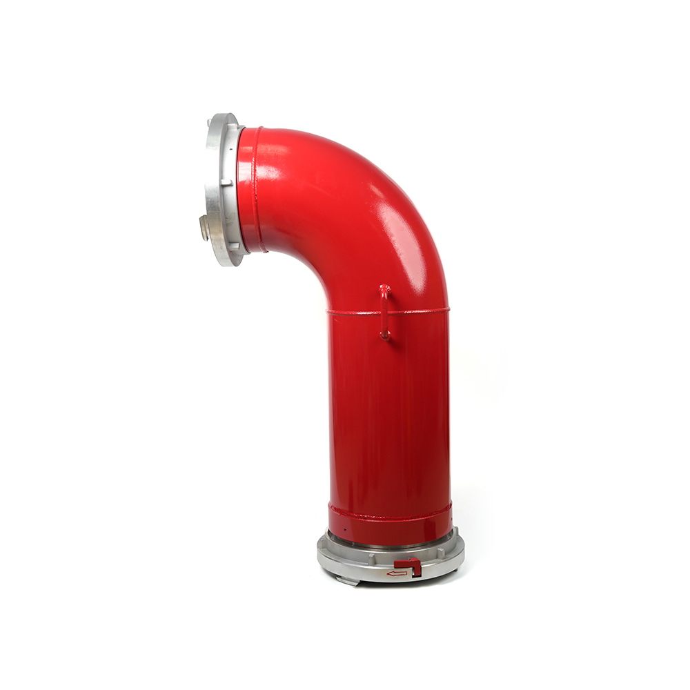
 Grooved Fire Elbow-Multi-tooth
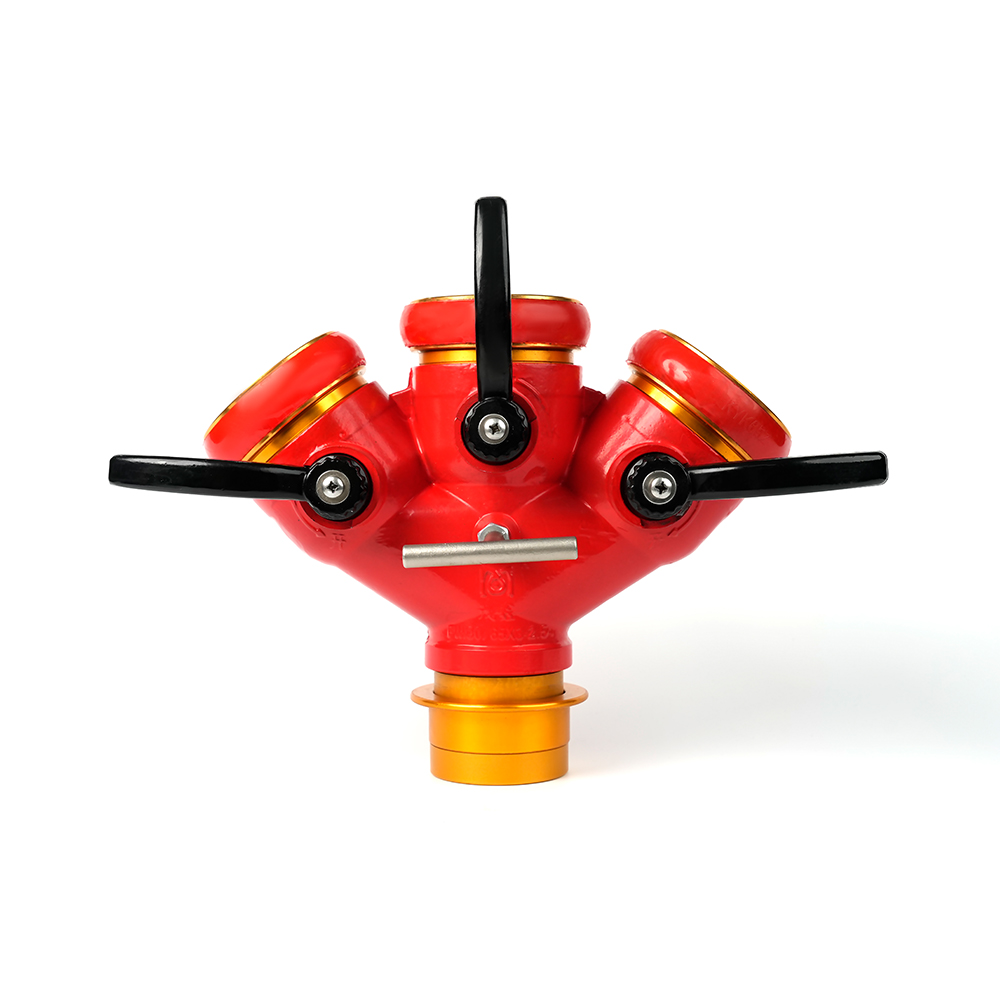
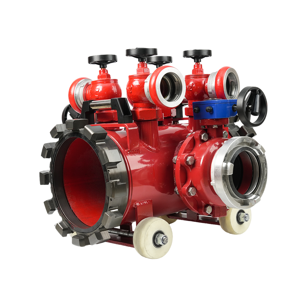 Multi-functional Fire Hose Distributor
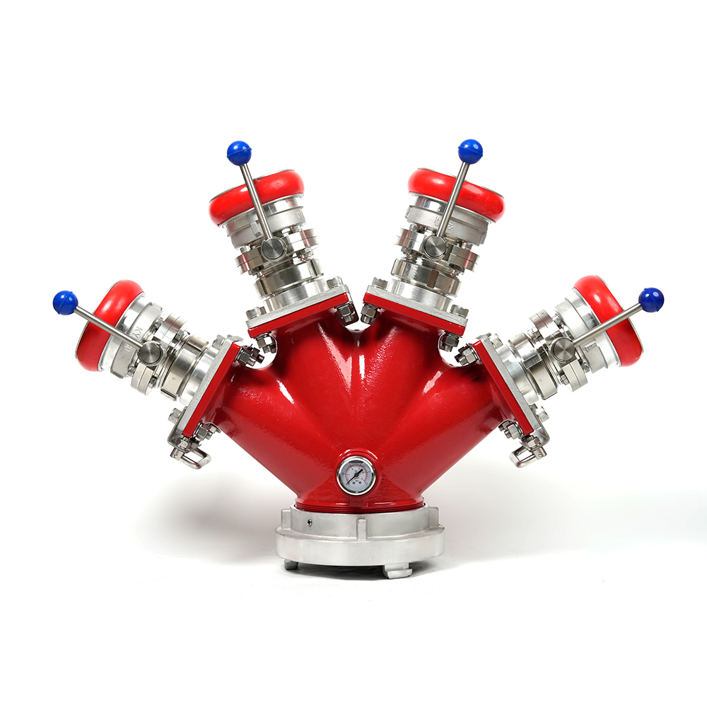 Locking Four-Way Fire Hose Distributor
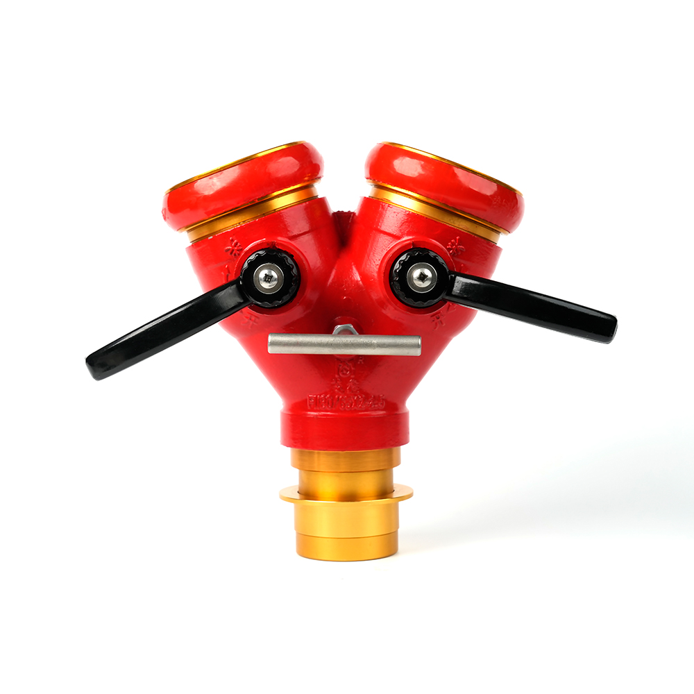
 Locking Three-Way Fire Hose Distributor
 Locking Two-Way Fire Hose Distributor
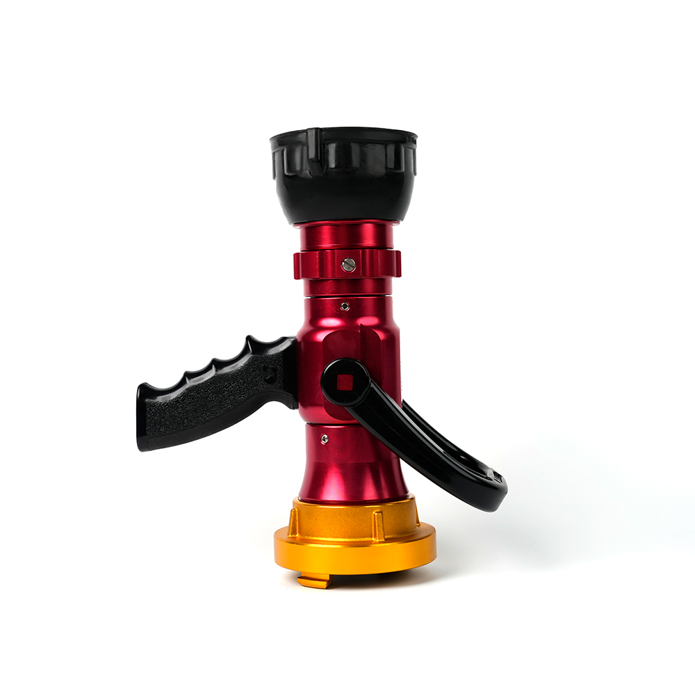
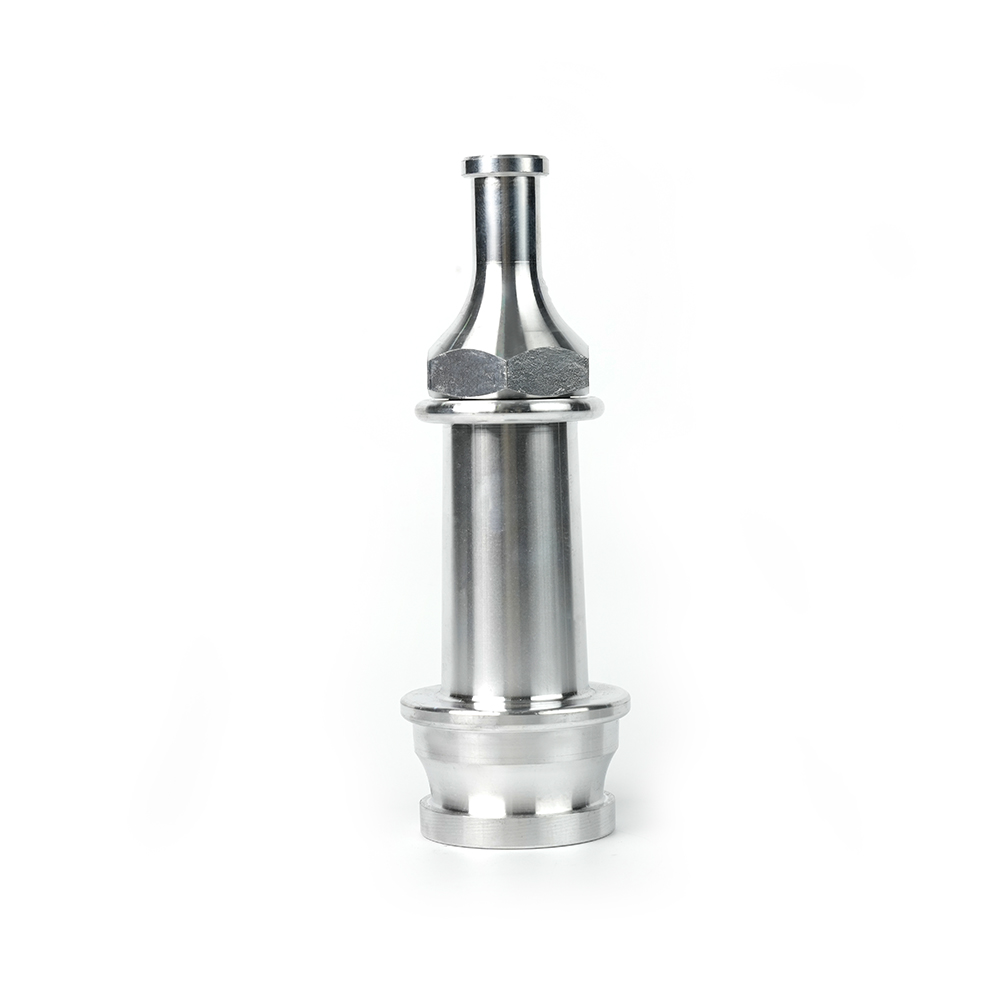 Straight Stream Nozzle
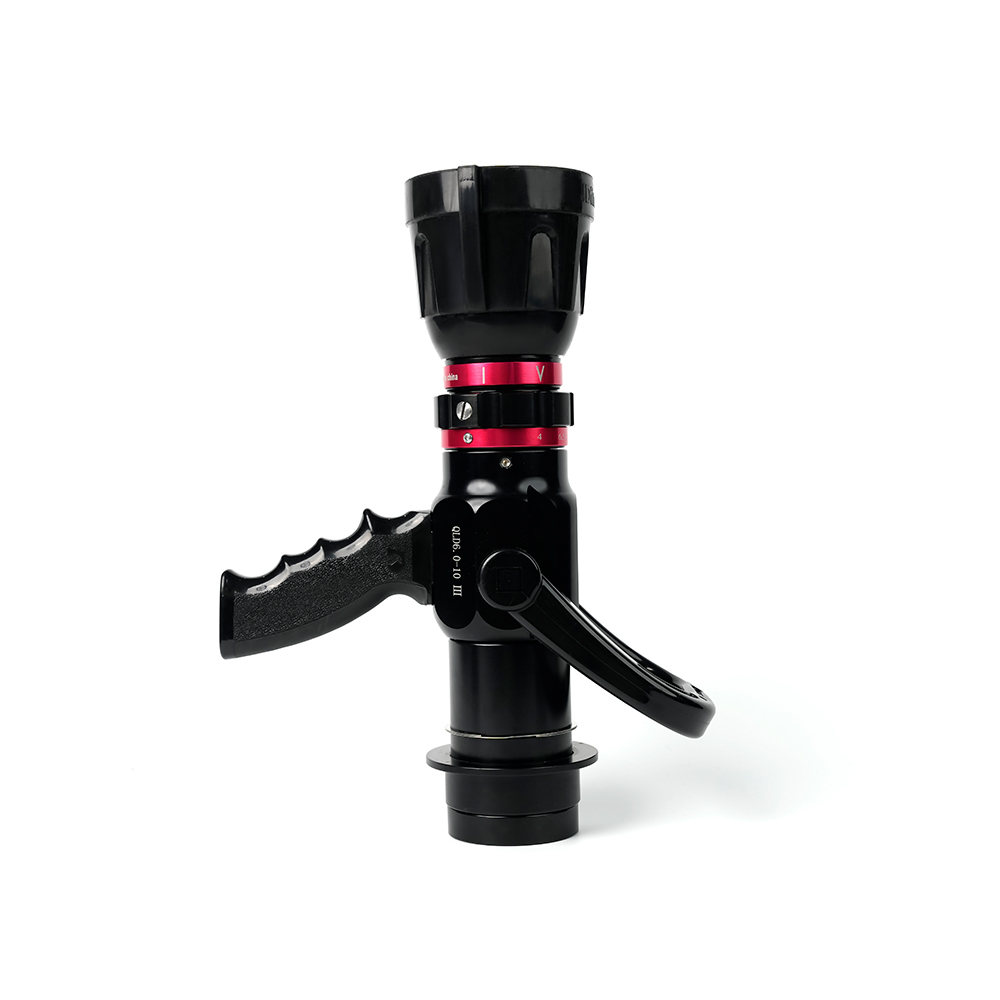 Adjustable nozzle-machino
 Adjustable nozzle-storz
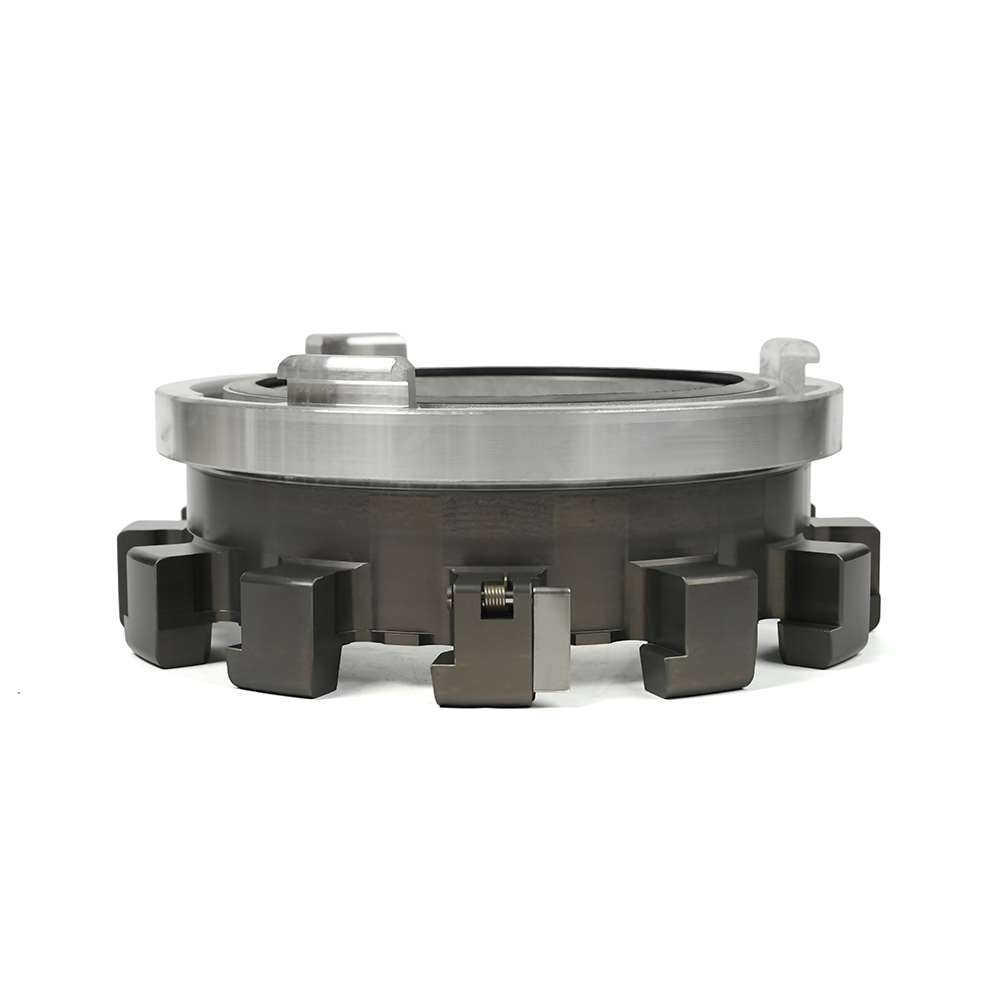 Storz Adapter Couplings - Multi-Tooth
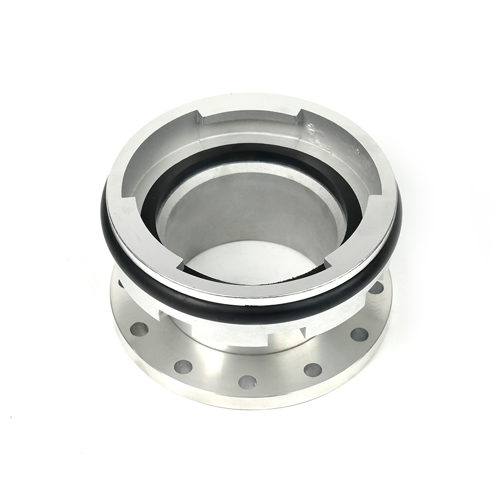 Machino Adapter Couplings – Flanged
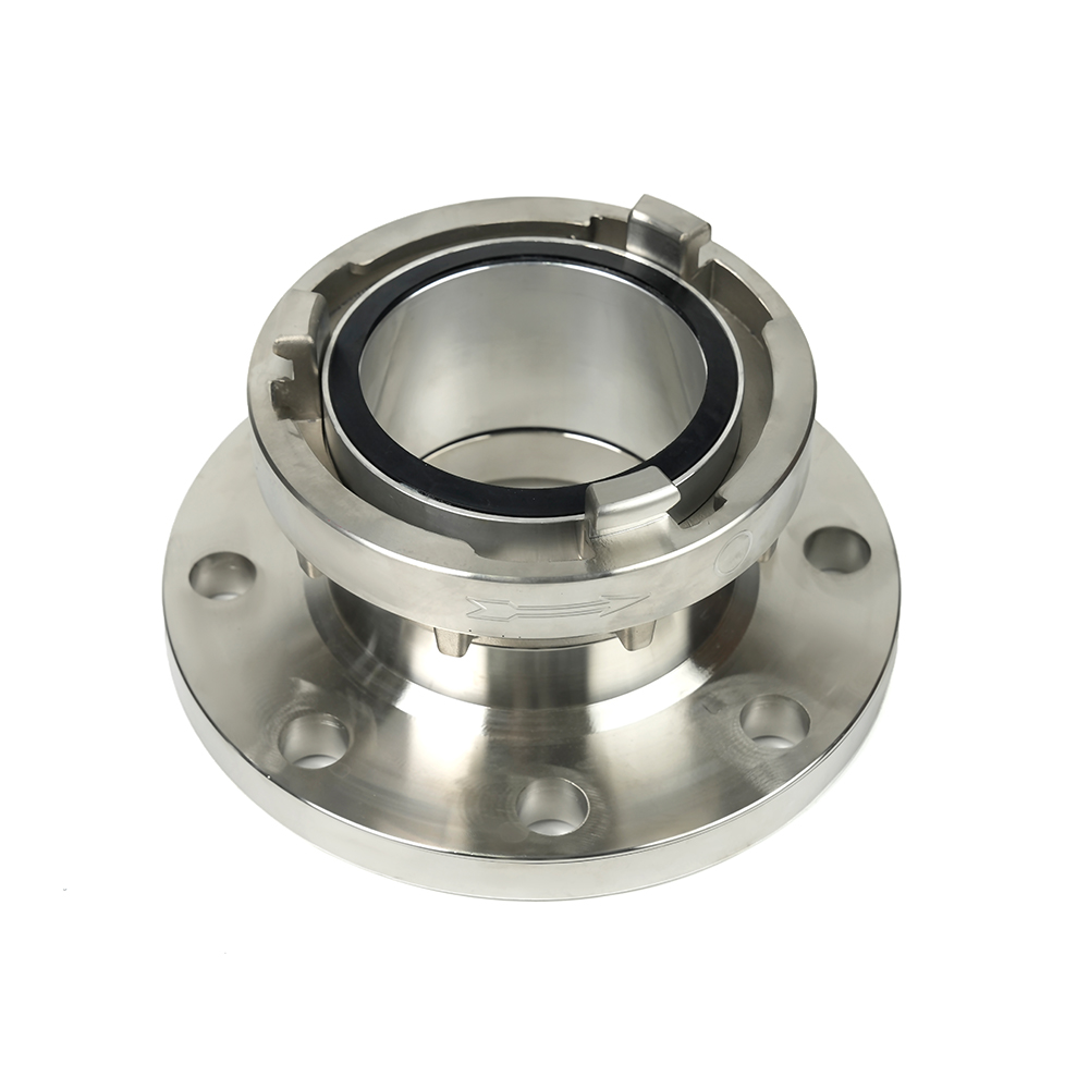 Storz Adapter Couplings – Flanged
 Contact Number
+86-0523-83274900
+86-151 9064 3365
 Let our team offer you customs solutions.
 Company Address
West side of Hongxing Middle Road, Lincheng Street, Development Zone, Xinghua City, Jiangsu Province, China
Copyright @Jiangsu Jinding Fire Protection Technology Co., Ltd. All rights reserved Fire Protection Equipments Manufacturers
