To check if an adapter coupling is faulty, inspect it systematically for physical damage, seal integrity, locking mechanism function, and leak-free performance under pressure.Most faults can be identified through a combination of visual inspection, manual functional testing, and a controlled pressure test before the coupling is returned to service.
Understand What Adapter Couplings Do and Where They Fail
Adapter couplings are transition fittings that allow two different coupling standards to be joined without modifying either connected component. Common types include:
- German to Storz (male/female) — converts between the German instantaneous coupling standard and the Storz symmetrical coupling system.
- German to Forestry — connects standard German couplings to forestry firefighting hose fittings.
- German to German Self-locking — standard German coupling adapted with an added self-locking retention mechanism.
- German to Flange — connects German-standard hose couplings to flanged pipe or equipment inlets.
- German to Multi-tooth — bridges German coupling systems with multi-tooth cam-and-groove style fittings.
- Storz male to Storz female / Storz to Forestry — converts between Storz variants or from Storz to forestry hose standards.
Because adapter couplings interface two different mechanical systems, they are subject to stress at both connection points simultaneously. The most common failure locations are the sealing gasket, the locking teeth or lugs, the body (especially at the transition zone between standards), and the external surface finish which can indicate corrosion or impact damage.
Step-by-Step Visual Inspection Procedure
Begin every check with a thorough visual inspection under adequate lighting. This step costs nothing and catches the majority of obvious faults before any functional testing begins.
Inspect the Coupling Body
- Look for cracks, fractures, or splits in the body, especially around the lugs, ears, and the transition shoulder between the two coupling standards.
- Check for dents or deformation from impact — even minor body distortion can prevent the coupling from seating correctly against its mating fitting.
- Examine the surface for corrosion, pitting, or heavy oxidation. On aluminum couplings, white powdery deposits (aluminum oxide) indicate moisture ingress and accelerated surface degradation. On brass couplings, green patina in pitted areas indicates dezincification risk.
- Confirm the body has no visible weld repairs, patches, or unauthorized modifications — these are grounds for immediate rejection.
Inspect the Locking Lugs and Teeth
- Examine all locking lugs, ears, or cam teeth for chipping, rounding, or cracking. Worn lug profiles are one of the leading causes of accidental decoupling under pressure.
- On Storz-type interfaces, check that the half-round locking lugs are symmetrical and undeformed. Asymmetrical wear indicates that the coupling has been connected at an angle repeatedly, causing uneven load on one lug.
- On self-locking German-type adapters, verify the locking spring or clip mechanism is present, intact, and correctly seated. A missing or bent spring will prevent the self-locking function from engaging.
Inspect the Sealing Gasket
- Remove the gasket if accessible and inspect it for compression set (permanent flattening), cracking, hardening, swelling, or extrusion damage.
- A gasket that has been compressed below 70% of its original thickness should be considered end-of-life and replaced, as it will no longer generate sufficient sealing force.
- Check that the gasket seats fully and evenly in its groove with no portion twisted, doubled over, or missing from the seating channel.
- Verify the gasket material is compatible with the fluid being carried — EPDM gaskets are standard for water and firefighting applications; NBR (nitrile) gaskets are required for petroleum-based fluids.
Functional Testing: Engagement, Rotation, and Release
After visual inspection, test the coupling's mechanical function by mating it with an appropriate counterpart fitting. This test confirms that the coupling performs its primary job — connecting and holding two fittings together — before pressure is applied.
- Test engagement — connect the adapter to its mating fitting by hand. The connection should engage smoothly and without excessive force. Resistance, binding, or the need to force the coupling together indicates misalignment, deformation, or dimensional non-conformance.
- Test locking — after engagement, attempt to pull the two halves apart axially without releasing the lock. On a correctly functioning coupling, no axial separation should be possible while the locking mechanism is engaged. Any axial play of more than 1–2 mm under hand pull force indicates worn or damaged locking geometry.
- Test rotation (Storz types) — Storz-type couplings should rotate through their full locking arc (typically 30° to 40°) without sticking, grinding, or requiring excessive torque. Stiff or gritty rotation indicates contamination, corrosion, or damaged lug surfaces.
- Test release — disengage the coupling and confirm it releases cleanly. A coupling that requires excessive force to disengage, or that partially sticks, may have deformed lugs or a swollen gasket that is creating interference.
- Check seating gap — when fully engaged, inspect the interface between the two coupling faces. There should be no visible gap around the circumference. An uneven or partially open face gap indicates that the gasket or sealing faces are not in full contact, which will result in leakage under pressure.
Pressure Testing to Confirm Leak-Free Performance
A coupling that passes visual and functional inspection should still be pressure tested before being returned to service in critical applications such as firefighting, hydraulic transfer, or pressurized process lines. Pressure testing is the only definitive method for confirming that the seal is intact under operating conditions.
Hydrostatic Test Procedure
- Connect the adapter coupling into a closed test assembly using appropriate blanking caps or a test bench manifold.
- Fill the assembly completely with water, purging all air, then pressurize to 1.5 times the coupling's rated working pressure — typically 15–25 bar for standard firefighting hose couplings.
- Hold the test pressure for a minimum of 60 seconds and inspect all interfaces, the coupling body, and the gasket zone for any seepage, dripping, or pressure drop on the gauge.
- Any pressure drop or visible moisture at the coupling face or body constitutes a test failure — the coupling must be disassembled, the fault identified, and the component either repaired with a new gasket or replaced entirely.
Common Fault Types and Their Likely Causes
| Observed Fault |
Likely Cause |
Action Required |
| Leaking at coupling face under pressure |
Worn, hardened, or missing gasket |
Replace gasket; retest |
| Coupling disengages under pressure |
Worn or chipped locking lugs / teeth |
Replace coupling — lug damage is not repairable |
| Difficult to engage or disengage |
Corrosion, contamination, or body deformation |
Clean and lubricate; replace if deformed |
| Leaking through coupling body |
Body crack or porosity from casting defect |
Remove from service immediately; replace |
| Visible gap at coupling interface when locked |
Gasket missing or lug geometry worn |
Inspect both gasket and lug profiles; replace as needed |
| Self-locking mechanism fails to hold |
Missing or deformed locking spring/clip |
Replace spring/clip; retest locking function |
| Heavy surface corrosion or pitting |
Prolonged moisture exposure or chemical contact |
Assess depth; replace if pitting penetrates wall thickness |
Common adapter coupling faults, their root causes, and the recommended corrective action for each.
Inspection Intervals and Maintenance Best Practices
Regular, scheduled inspection is far more effective than reactive fault-finding after a failure has occurred. The recommended inspection frequency depends on the application and environment:
- After every use — in firefighting or emergency response applications, visually inspect every adapter coupling after each deployment. Check for impact damage, gasket condition, and lug wear before returning equipment to the ready state.
- Every 6 months — perform a full visual, functional, and pressure test on all adapter couplings in standby inventory. Standards such as DIN 14811 (for German firefighting couplings) recommend biannual testing as a minimum.
- After any impact or drop event — always inspect an adapter coupling that has been dropped onto a hard surface or struck by equipment, even if no visible damage is apparent. Hidden cracks in casting alloys may not be externally visible but will fail under pressure.
- Annual gasket replacement — in high-use or outdoor-stored applications, replace gaskets on a fixed annual schedule regardless of apparent condition. Gasket material (especially EPDM and NBR) degrades through UV exposure, ozone, and thermal cycling even when not in service.
After cleaning, lightly lubricate the lug surfaces and gasket with a compatible lubricant (silicone grease for EPDM gaskets; petroleum jelly is not recommended as it degrades rubber gaskets). Store adapter couplings in a dry location away from UV exposure and chemical vapors to maximize service life between inspections.
When to Replace Rather Than Repair an Adapter Coupling
Not all faults are repairable. Some conditions require immediate removal from service and full replacement of the adapter coupling, regardless of cost considerations:
- Any crack in the coupling body — cracks propagate under pressure and cannot be safely welded or patched in pressure-carrying couplings.
- Lug or tooth damage beyond minor wear — chipped, fractured, or heavily rounded lug geometry cannot be restored and will result in unreliable locking.
- Body wall thickness reduced by corrosion — if pitting has penetrated more than 20% of the nominal wall thickness, the structural integrity under pressure cannot be assured.
- Failure to hold pressure after gasket replacement — if a coupling continues to leak after a new correctly-fitted gasket has been installed, the sealing face of the body is likely damaged and the coupling body must be replaced.
- Unknown service history or age beyond service life — adapter couplings without traceable inspection records, or those exceeding the manufacturer's recommended service life (typically 10–15 years for aluminum firefighting couplings), should be retired from pressure service regardless of apparent condition.
 英语
英语 西班牙语
西班牙语 德语
德语
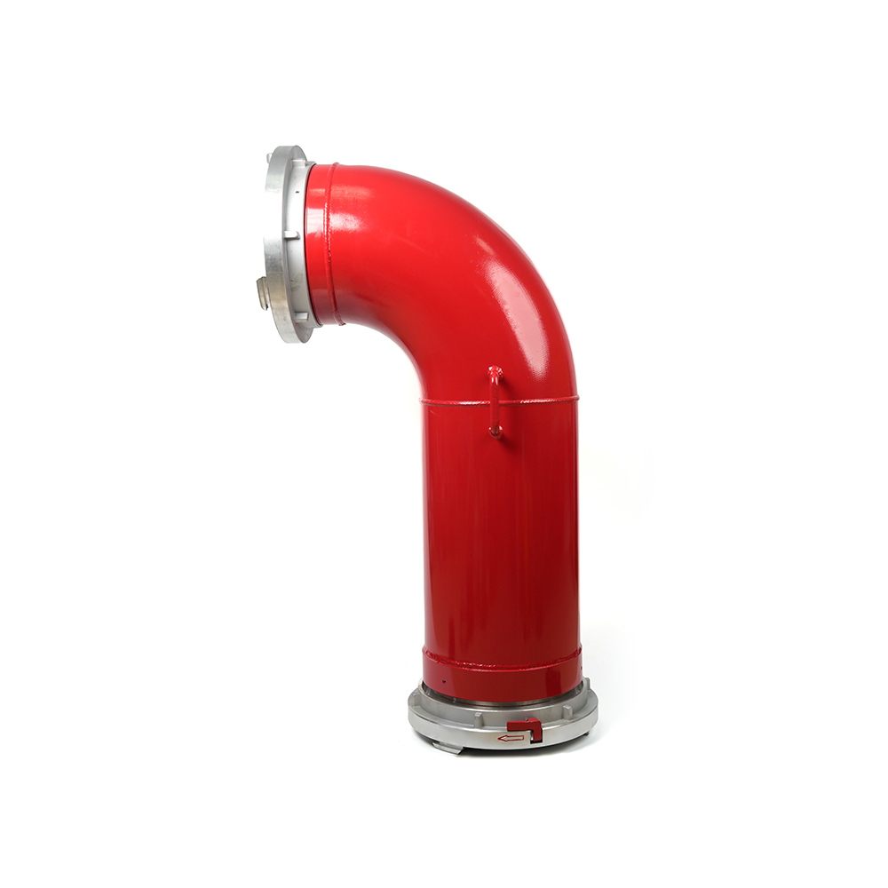 Grooved Fire Elbow-Storz
 Grooved Fire Elbow-Multi-tooth
 Multi-functional Fire Hose Distributor
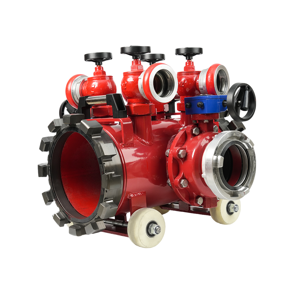
 Locking Four-Way Fire Hose Distributor
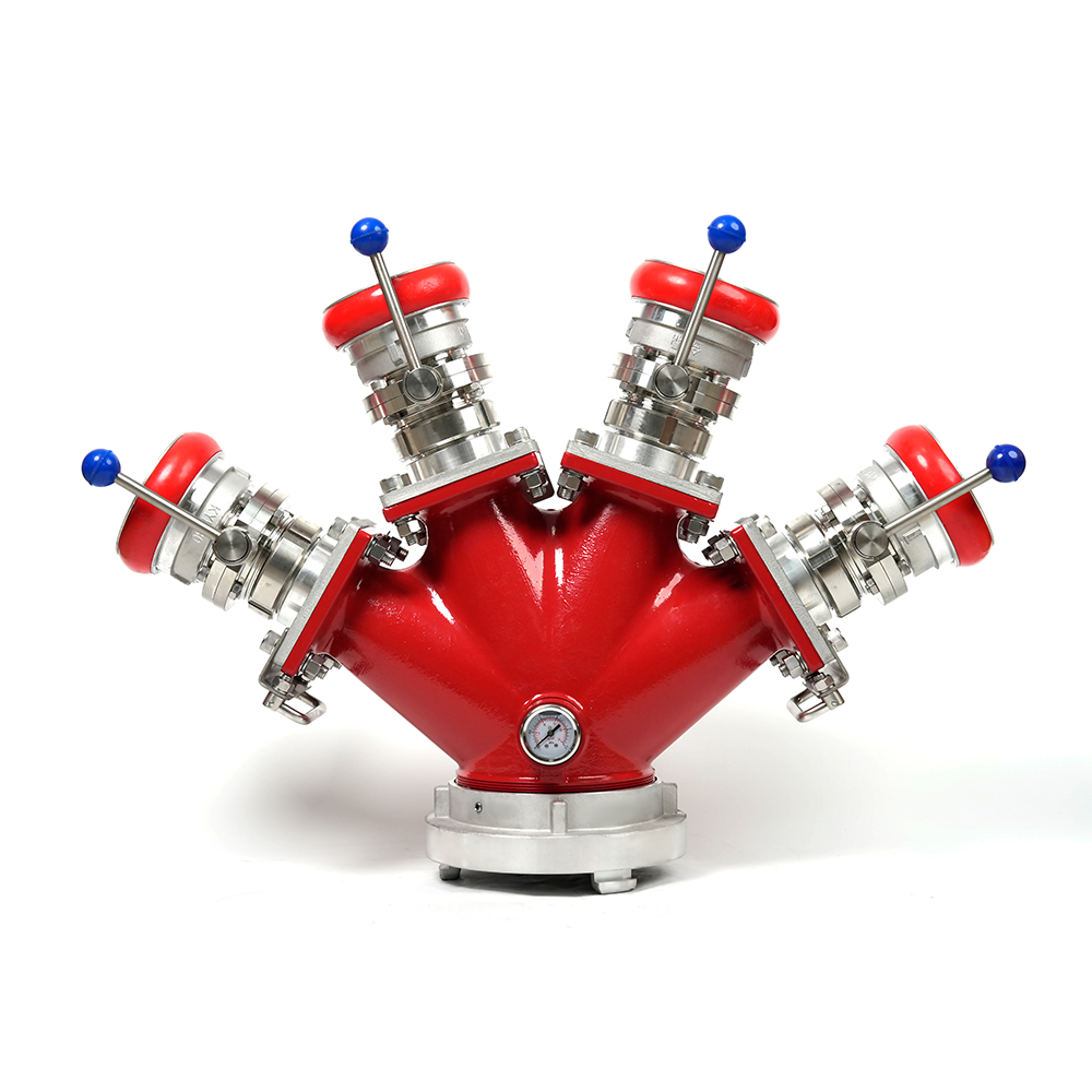
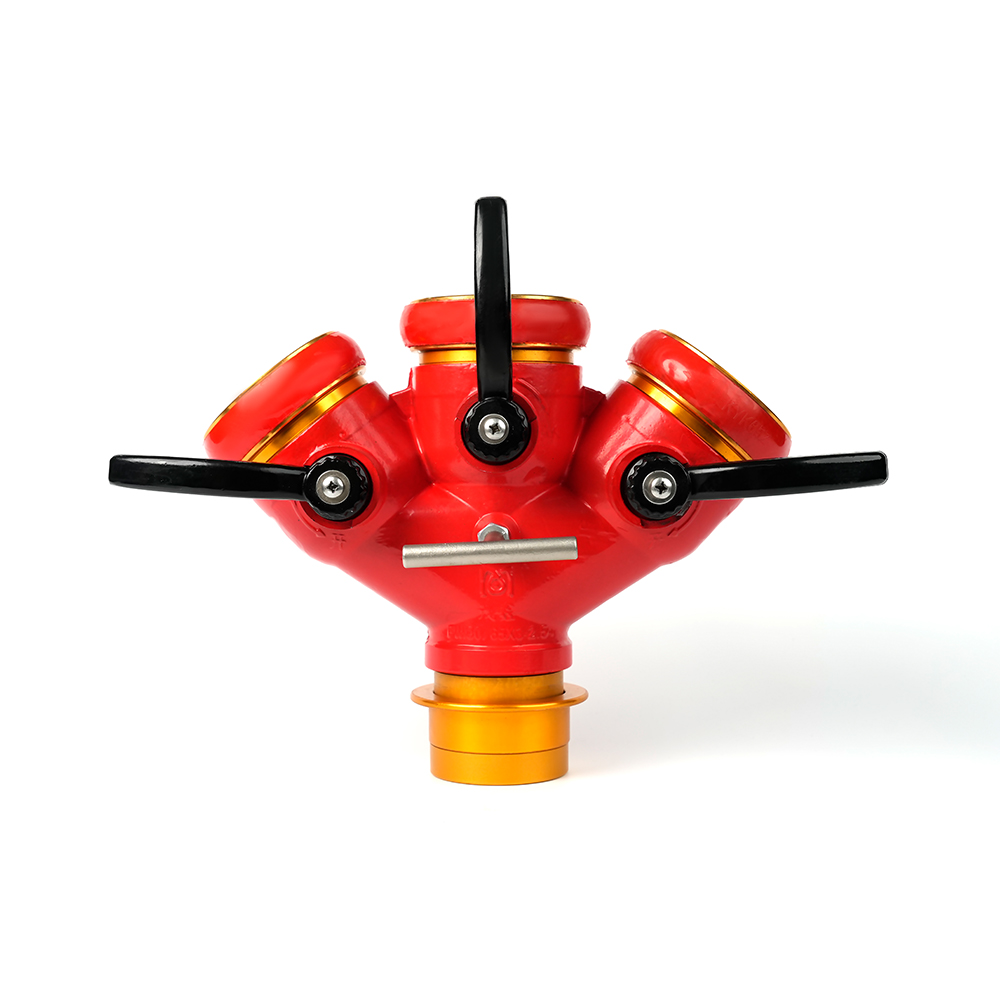 Locking Three-Way Fire Hose Distributor
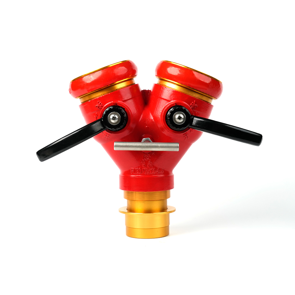 Locking Two-Way Fire Hose Distributor
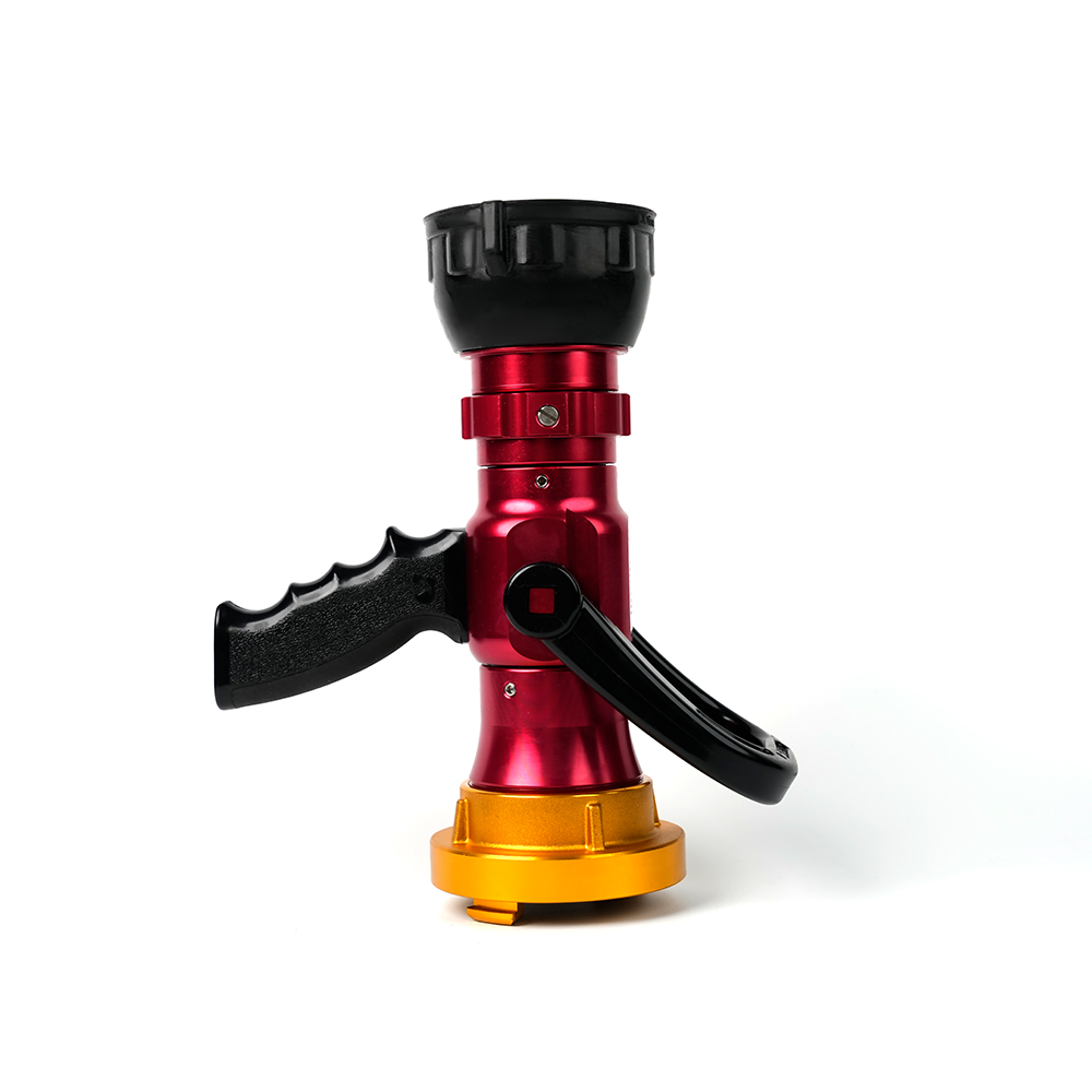
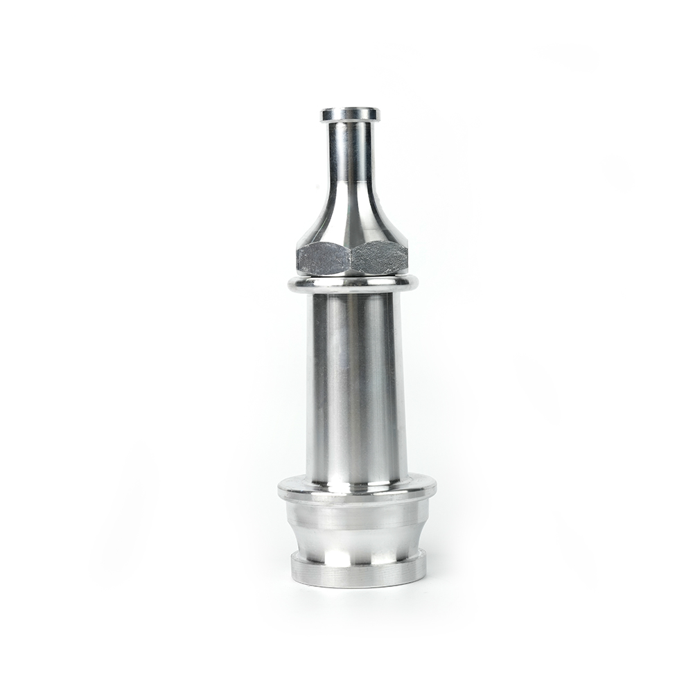 Straight Stream Nozzle
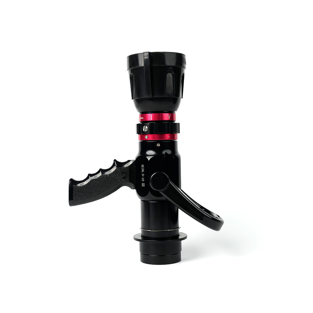 Adjustable nozzle-machino
 Adjustable nozzle-storz
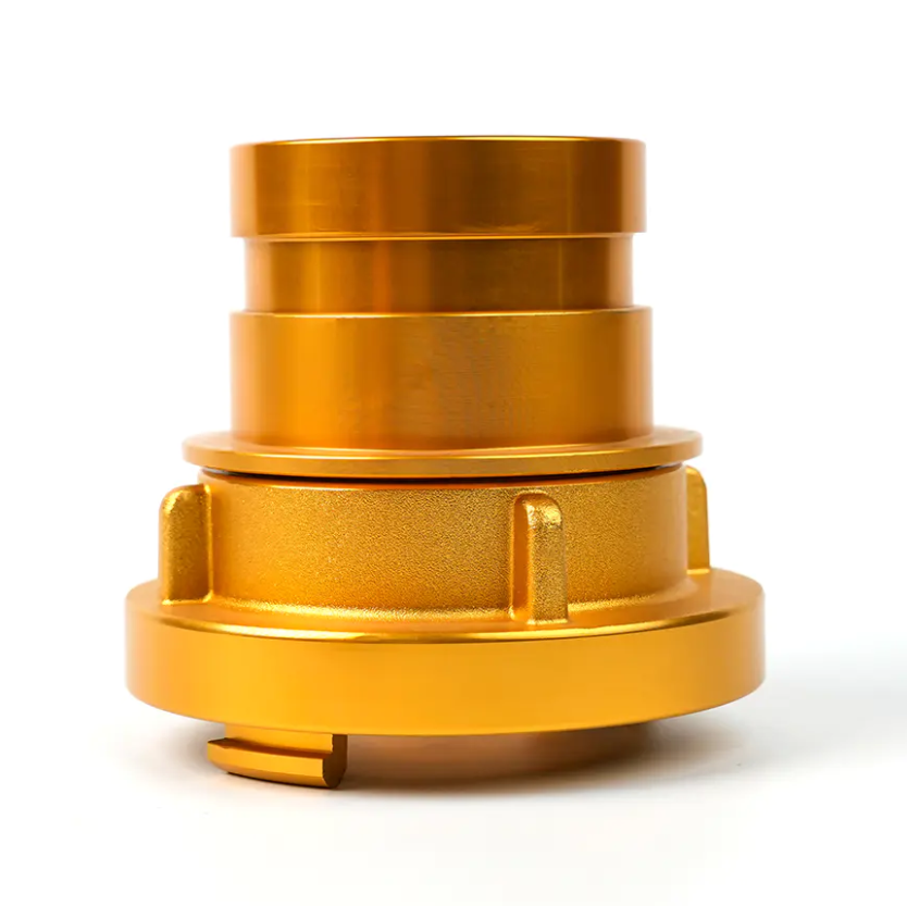
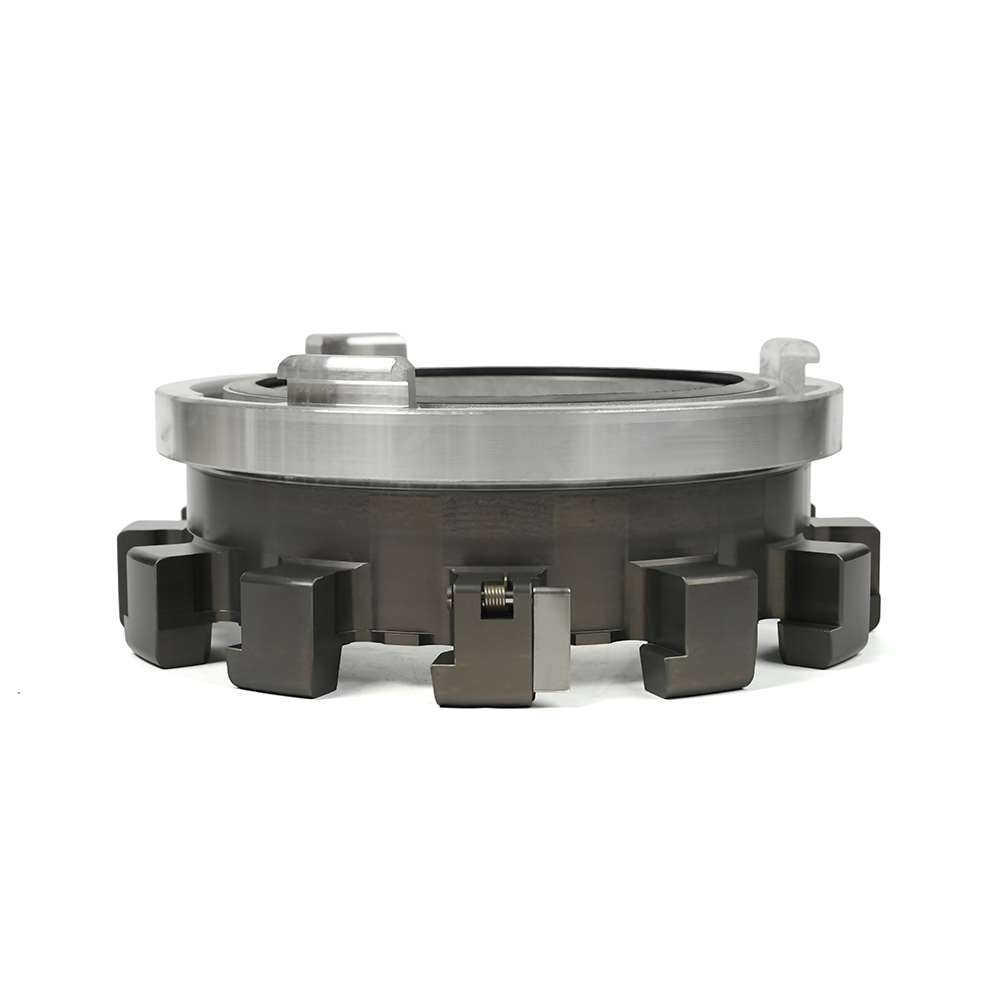 Storz Adapter Couplings - Multi-Tooth
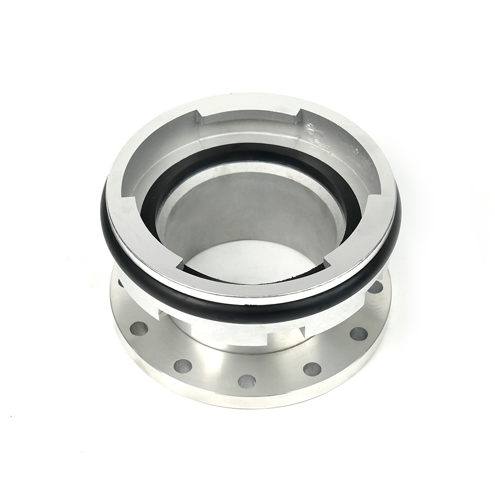 Machino Adapter Couplings – Flanged
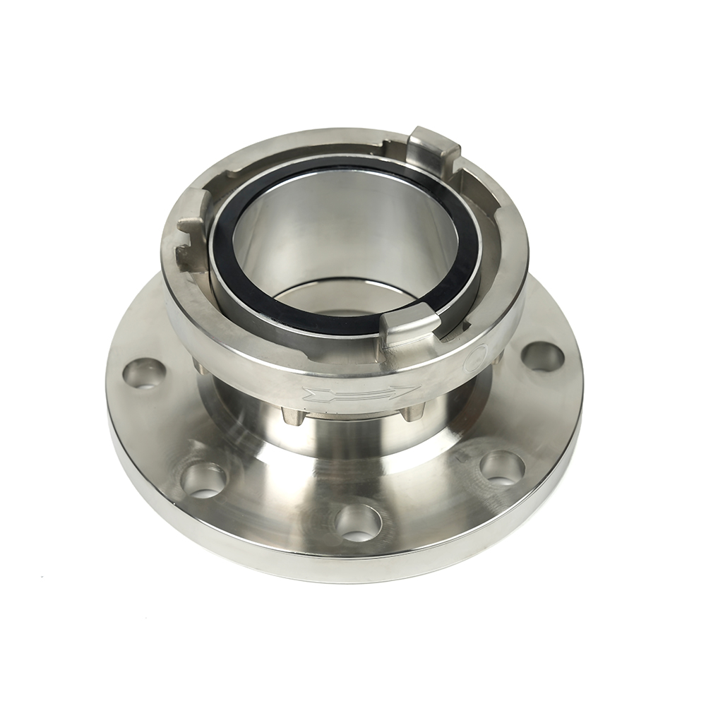 Storz Adapter Couplings – Flanged
 Contact Number
 Let our team offer you customs solutions.
 Company Address
