 英语
英语 西班牙语
西班牙语 德语
德语Industry News

GET IN TOUCH
+86-0523-83274900
+86-151 9064 3365
Content
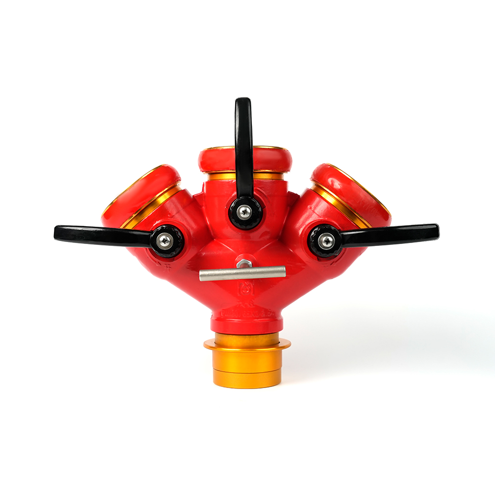
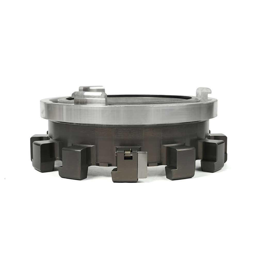
A locking fire hose distributor is a firefighting water-splitting device equipped with an anti-misoperation locking mechanism that divides a single pressurised water supply into multiple independent outlet streams, each controlled by its own valve. The defining feature — the locking mechanism — physically prevents valves from being opened or closed accidentally under pressure, ensuring that each outlet can only be operated by a deliberate, authorised action. This makes the locking distributor essential in complex firefighting operations where simultaneous multi-line water delivery must be managed safely under high-pressure conditions, including high-rise building fire suppression, forest firefighting, chemical plant emergencies, and command vehicle deployment.
A fire hose distributor — also called a water divider, manifold, or wye divider depending on the outlet count and regional terminology — connects to a single inlet water supply and routes the flow through an internal manifold body to multiple outlets. Each outlet incorporates a ball valve, gate valve, or quarter-turn valve that allows the outlet to be opened, partially throttled, or completely closed independently of the other outlets.
In a standard (non-locking) distributor, each valve can be operated freely by anyone on the fireground who reaches it. In high-pressure systems where the inlet pressure may reach 10–16 bar (145–232 psi) or more, an accidentally opened or closed valve can cause catastrophic consequences: a sudden pressure surge can rupture a connected hose or knock over a firefighter at the nozzle; an unexpected closure can deprive a crew of water at a critical moment.
The locking mechanism addresses this risk directly. It may take the form of a physical lock pin, a rotation-and-lock collar, a keyed lock, or a safety clasp that must be disengaged before the valve handle can be moved. In all configurations, the lock serves the same function: it requires a deliberate two-step action to change valve state, making accidental actuation essentially impossible under normal operating conditions.
Understanding the physical components of a locking distributor helps fire service procurement officers, system designers, and operational crews specify and use equipment correctly.
The difference between a standard distributor and a locking distributor is not an incremental improvement — it represents a fundamental change in how valve authority is managed on the fireground. Several specific hazard scenarios illustrate why this matters in practice.
In large-scale firefighting operations, multiple personnel may be working in close proximity to a distributor. Hose lines, equipment, and personnel movement create physical contact with the distributor body. Without a locking mechanism, a hose under tension or a firefighter losing balance could inadvertently close or open a valve — instantly depriving a crew of water or over-pressurising a line that was being held closed. A locking mechanism eliminates this scenario entirely by requiring intentional disengagement before the valve can be moved.
At major incidents that extend over hours — building fires, industrial site emergencies, wildland interface fires — the distributor may be left unattended at a water supply point while crews are deployed at the fire front. Without locking, any person reaching the distributor can change valve states without the knowledge of the water supply officer. The locking mechanism preserves the valve configuration set by the incident commander and prevents unauthorised changes that could disrupt coordinated water management.
The locking mechanism also enforces a slower, more deliberate valve operation by requiring the lock to be disengaged first. This inherently prevents operators from slamming a valve fully open or closed in a single rapid motion — a behaviour that generates water hammer and pressure surges. In a distribution system operating at 10 bar with a 65 mm hose line, a sudden valve slam can generate surge pressures two to three times the operating pressure, sufficient to rupture older hose sections or blow couplings apart.
Locking fire hose distributors are manufactured in outlet configurations ranging from two to four (or more) outlets, with the choice depending on the number of attack lines or water delivery points required at the incident.
| Configuration | Typical Inlet Size | Typical Outlet Size | Common Applications |
|---|---|---|---|
| Two-way (Wye) | 65 mm or 70 mm | 2 × 45 mm or 2 × 52 mm | Structural fire attack, hydrant splitting, two-crew operations |
| Three-way | 80 mm or 100 mm | 3 × 52 mm or 3 × 65 mm | High-rise building fire, command vehicle deployment, multi-sector supply |
| Four-way | 100 mm | 4 × 52 mm or 4 × 65 mm | Forest firefighting, industrial site emergencies, large-area water distribution |
The total flow capacity of the distributor must be sufficient to supply all outlets simultaneously at their minimum required flow rates. A three-way distributor supplying three 65 mm attack lines at 400 litres per minute each requires an inlet supply capacity of at least 1,200 litres per minute — a specification that must be confirmed against the pumping appliance or hydrant output before deploying the distributor in that configuration.
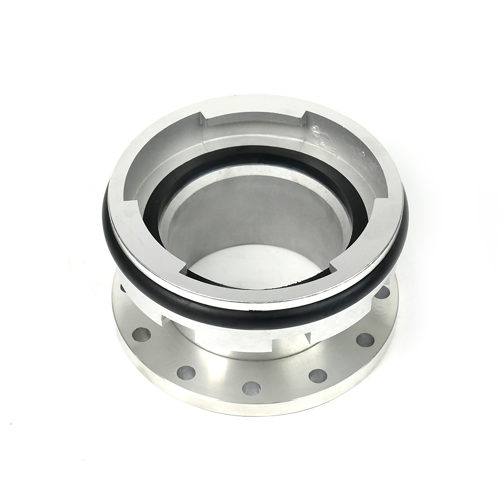
The coupling type on both inlet and outlet ports must match the fire service standard in use at the deployment location. Locking distributors are available with — or can be customised to — the major international coupling standards used in firefighting and industrial fire protection.
The body material and pressure rating of a locking distributor determine its suitability for the operating conditions of the intended application. Selecting an under-rated or inappropriately materialised distributor creates both safety and operational reliability risks.
The most widely used material for portable locking distributors. Aluminium alloy bodies are lightweight — a three-way 65 mm aluminium distributor typically weighs 1.5–2.5 kg without water — making them practical for manual deployment and repositioning during operations. Aluminium is corrosion-resistant, accepts anodising and powder coating for additional protection, and provides adequate strength for working pressures of 16 bar (232 psi) — the standard maximum operating pressure for most fire service portable equipment. Not recommended for applications with prolonged exposure to highly concentrated chemical environments.
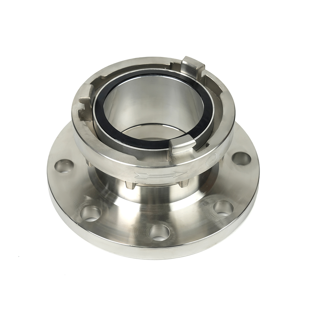
Brass distributors provide superior corrosion resistance compared to aluminium, particularly in coastal or marine environments where salt air accelerates corrosion. Brass is also fully compatible with the broadest range of firefighting chemical agents and foam concentrates. The trade-off is weight — a comparable brass distributor may weigh 40–60% more than its aluminium equivalent — which can be significant for portable deployment in extended operations. Brass is the preferred material for fixed industrial installations and permanent fire protection systems.
Used in large-diameter, high-pressure permanent installations. Ductile iron provides higher impact resistance than aluminium and handles sustained high-pressure operation reliably, but its weight makes it unsuitable for portable applications. Pressure ratings for ductile iron distributors can reach 25 bar (363 psi) or above for specialised industrial applications.
The locking fire hose distributor is deployed wherever a single water supply point must serve multiple simultaneous hose lines, and where safe, controlled valve management is operationally critical.
In tall buildings, water is supplied to upper floors through vertical dry risers or wet riser mains with limited outlet points. A locking distributor fitted at the riser outlet allows a single riser connection to supply multiple attack teams on the fire floor and adjacent floors simultaneously. The locking mechanism prevents one team from accidentally interrupting another team's water supply by inadvertently changing valve state while moving equipment around the riser outlet.
In forest firefighting, water is typically drawn from portable pumps, water tenders, or static supply points at significant distances from the fire front. Portable locking distributors allow a single pump outlet to supply multiple hose lines along a firebreak or access track, enabling simultaneous attack on a broad fire perimeter front. Four-way configurations with 65 mm outlets allow a single high-capacity pump to supply four independent hose lines, each capable of delivering sufficient flow for a two-person attack crew.
Industrial fire protection in high-risk process environments uses locking distributors at fixed deluge system inlets, foam system manifolds, and portable water supply points. The anti-misoperation lock is particularly important in these settings, where accidental water application to certain process areas or equipment can cause secondary incidents (steam explosions, electrical faults, chemical reactions) as serious as the original fire. The locking mechanism provides an operational control layer that prevents uncoordinated valve operation by personnel who are not part of the incident command structure.
Command vehicles and water relay pumping appliances use locking distributors to manage the distribution of water from tender-to-tender relays or large-diameter supply lines to multiple operational sectors at major incidents. The distributor is managed by a dedicated water supply officer who controls all outlet valve operations — the locking mechanism ensures that only the water supply officer can change valve states, maintaining centralised control of the water supply plan throughout the incident.
Locking fire hose distributors are life-safety equipment that must be maintained in fully serviceable condition at all times. The following inspection and maintenance practices are standard across professional fire services:
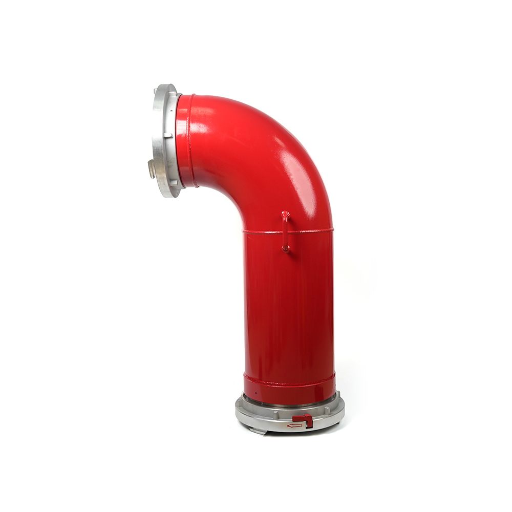 Grooved Fire Elbow-Storz
 Grooved Fire Elbow-Multi-tooth
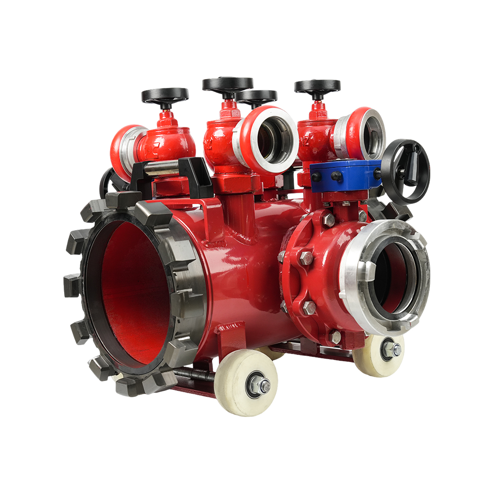 Multi-functional Fire Hose Distributor
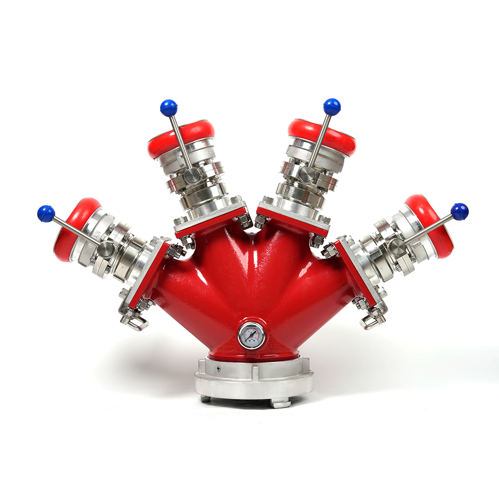 Locking Four-Way Fire Hose Distributor
 Locking Three-Way Fire Hose Distributor
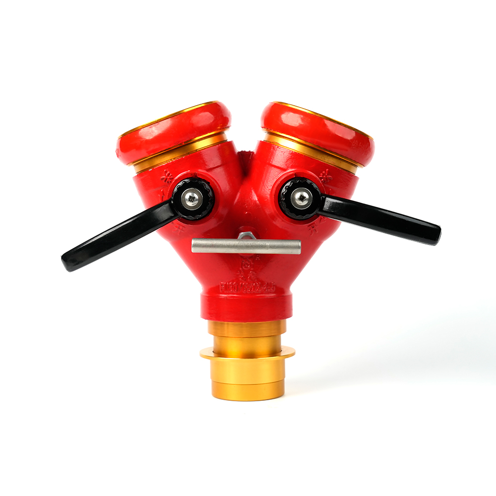
 Locking Two-Way Fire Hose Distributor
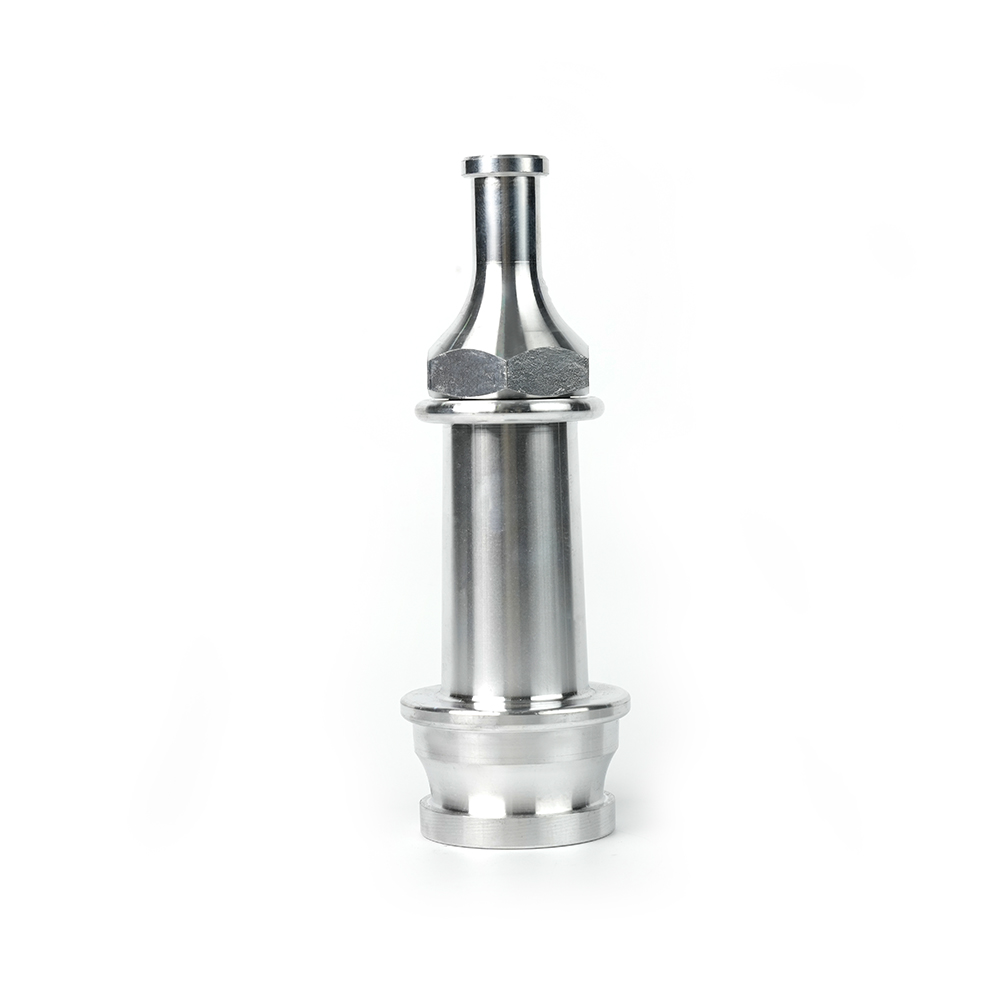 Straight Stream Nozzle
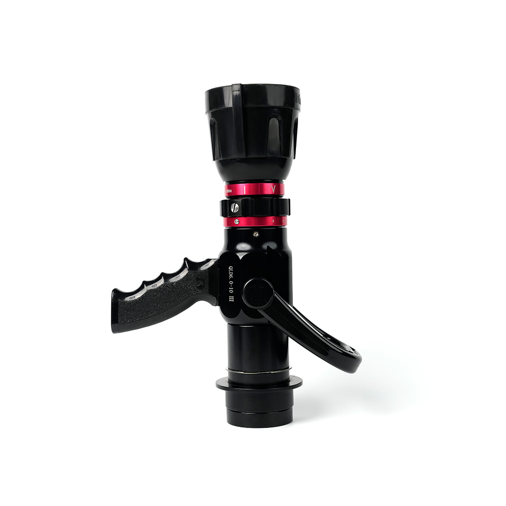 Adjustable nozzle-machino
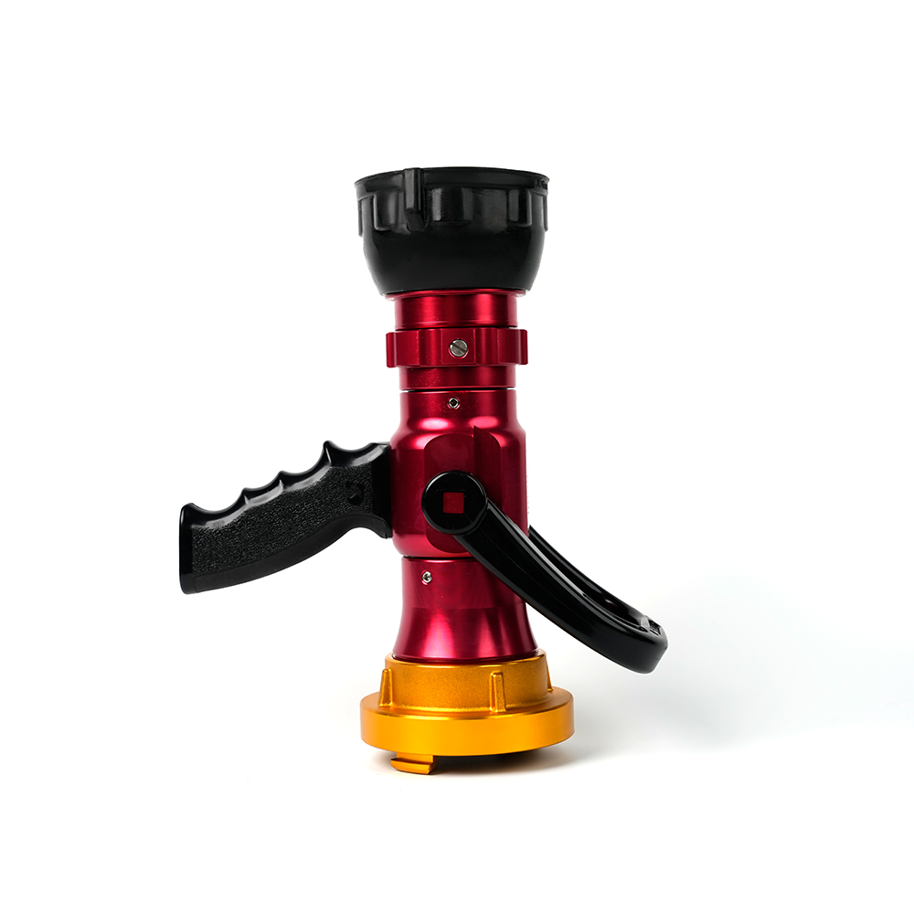 Adjustable nozzle-storz
 Storz Adapter Couplings - Multi-Tooth
 Machino Adapter Couplings – Flanged
 Storz Adapter Couplings – Flanged
 Contact Number
+86-0523-83274900
+86-151 9064 3365
 Let our team offer you customs solutions.
 Company Address
West side of Hongxing Middle Road, Lincheng Street, Development Zone, Xinghua City, Jiangsu Province, China
Copyright @Jiangsu Jinding Fire Protection Technology Co., Ltd. All rights reserved Fire Protection Equipments Manufacturers
