 英语
 西班牙语
 德语
Industry News
Home / News / Industry News / Fire Hydrant Valve Explained: Main Valve, Drain Ports, Outlet Fittings


+86-0523-83274900
+86-151 9064 3365
Content
Water trapped in a hydrant barrel after the main valve closes causes more winter failures than worn seats or stripped stems. That single fact explains why dry barrel hydrants are built around two separate mechanisms: the main valve that releases water to the outlets, and the drain valve that empties the barrel the moment the main valve seats again. Understand how the two work together and most buying, installation and maintenance decisions become straightforward.
The short answer to how a fire hydrant valve works: the operating nut turns a stem, the stem lifts a valve off its seat, water rises from the main into the barrel and leaves through the outlet connections, and once the valve closes again the drain ports reopen so the barrel can empty below the frost line. Specification mistakes and field failures almost always come from the details inside that loop.
In a dry barrel hydrant the valve sits at the bottom of the barrel, below the frost line. The operating nut drives a threaded stem through the bonnet, and the stem moves the valve assembly relative to a seat. Which direction the disc travels depends on the design, but the principle is constant: the seat separates the pressurised main from the empty barrel, and every seal along that path has to hold the rated pressure while the valve is closed.
Compression is the most common arrangement. The disc closes down onto the seat, so system pressure pushes the disc into the seat rather than away from it. Sealing is good, but the stem must open the valve against full pressure, which is why stem diameter, thread quality and the strength of the operating nut matter far more than they look. A stem that strips under a fire ground wrench ends the hydrant's usefulness immediately.
Wet barrel hydrants, used where frost is not a design driver, work differently. Water stands in the barrel permanently and each outlet carries its own small valve, so one outlet can be opened without pressurising the others. That is convenient for testing but puts more seals into the assembly.
| Valve style | How it operates | Typical application | What to verify |
|---|---|---|---|
| Compression valve | Disc closes down onto a seat and opens against line pressure | Dry barrel hydrants in freezing climates | Stem thread quality, replaceable seat, operating torque |
| Slide gate valve | Gate slides sideways clear of the port | Higher flow hydrant bodies and industrial headers | Guide rail wear, full travel clearance |
| Butterfly valve | Quarter turn disc mounted on a shaft | Compact wet barrel and plant hydrant assemblies | Disc edge seal wear, shaft bearings |
| Independent outlet valve | One small valve per outlet on the barrel | Wet barrel hydrants in frost free regions | Seal condition at each outlet, cap gaskets |
Standards set the baseline: AWWA C502 for dry barrel hydrants, AWWA C503 for wet barrel, EN 14384 for pillar hydrants, BS 750 for underground and above ground hydrants, and GB 4452 in China. A nominal rating of PN10 or PN16 covers most municipal networks, but industrial sites and refineries often specify higher shell and seat test pressures. Confirm the test values, not only the nominal rating.
When the main valve closes, the drain mechanism opens. In many designs a collar on the stem lifts clear of the drain seat, letting water in the barrel escape through drain holes at the base into a gravel bed. The sequence matters: on opening, the main valve lifts first and the drain closes before pressurised water arrives, so water is not forced out of the drain holes into the surrounding soil.
The chain fails when the gravel bed is missing, when drain holes are blocked by soil, roots or concrete, or when a hydrant is set out of plumb so the drain never fully closes. Symptoms appear far from the cause: a barrel that splits in the first freeze, or a hydrant that weeps at the flange after shutoff. At commissioning, pour a bucket of water into the barrel with the valve closed and watch it disappear. If it does not, fix the drainage before handing the unit over.
A working valve with the wrong outlet is a hydrant nobody can use. Valve bodies are typically DN80 or DN100, feeding one large outlet and one or two smaller ones, and the coupling on each outlet follows local practice. Storz dominates in Germany and much of Europe, Machino in Japan and parts of Asia, NH threads in North America, John Morris in the United Kingdom, and Italian couplings in Italy. Caps must match those standards exactly, and the gaskets inside them must suit the water and climate.
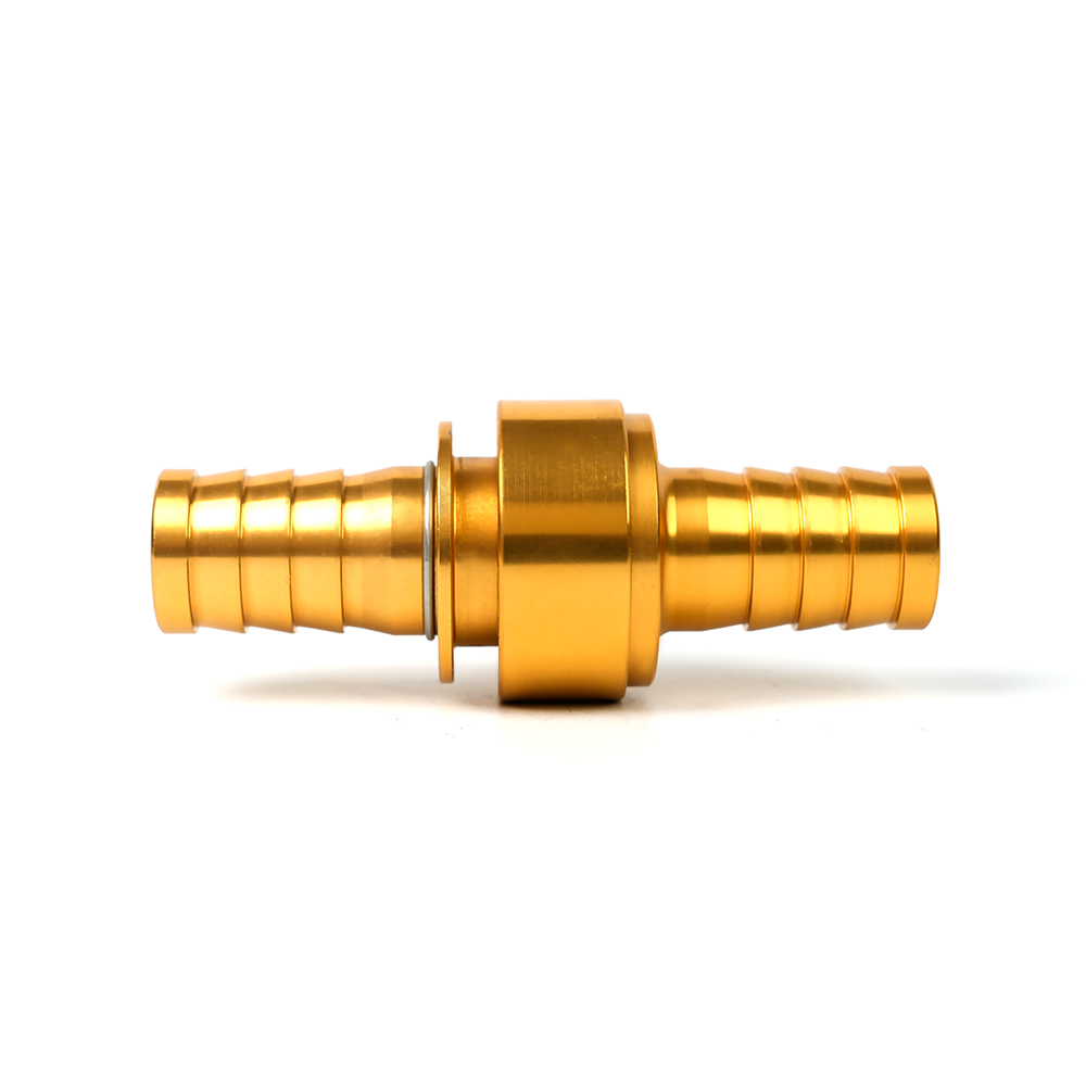 Machino Fire Hose Coupling for Hydrant OutletsAvailable in serrated or ribbed tail designs and DIN sizes, this coupling suits Machino-standard hydrant outlets and fire hose connections.View Product →
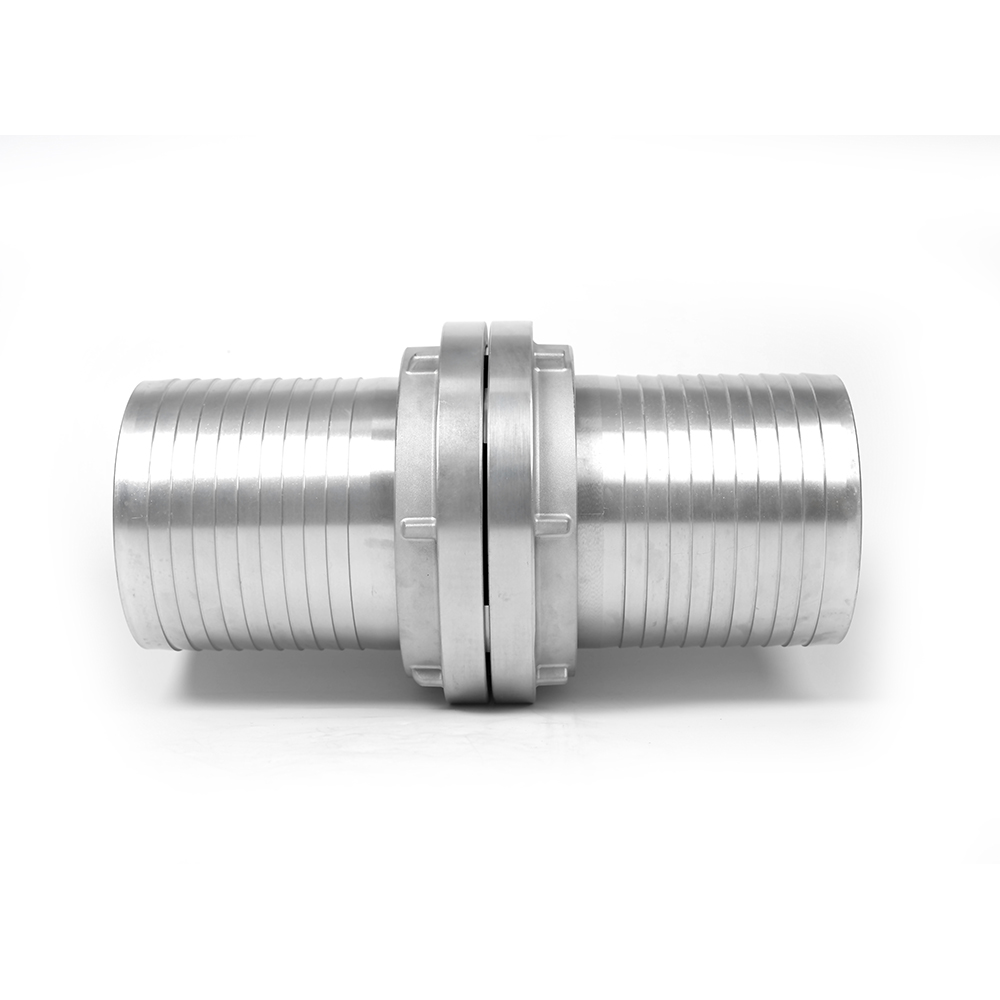 Large Storz Fire Hose CouplingA large-size Storz coupling with serrated or ribbed tail ends, offered in multiple sizes for fire hose connections across industrial applications.View Product →
Two practical rules. First, every outlet on one hydrant should be documented on the purchase order by standard, size and thread, because photographs rarely reveal thread differences. Second, keep outlet standards consistent across a fleet; mixed hydrants slow crews down and multiply the adapters a truck has to carry.
Blank caps protect outlet threads, keep debris and insects out of the barrel, and retain the gasket that seals the outlet. Lost caps are one of the most common maintenance issues on any network, so spares should be ordered with the hydrants and sized to the same standard.
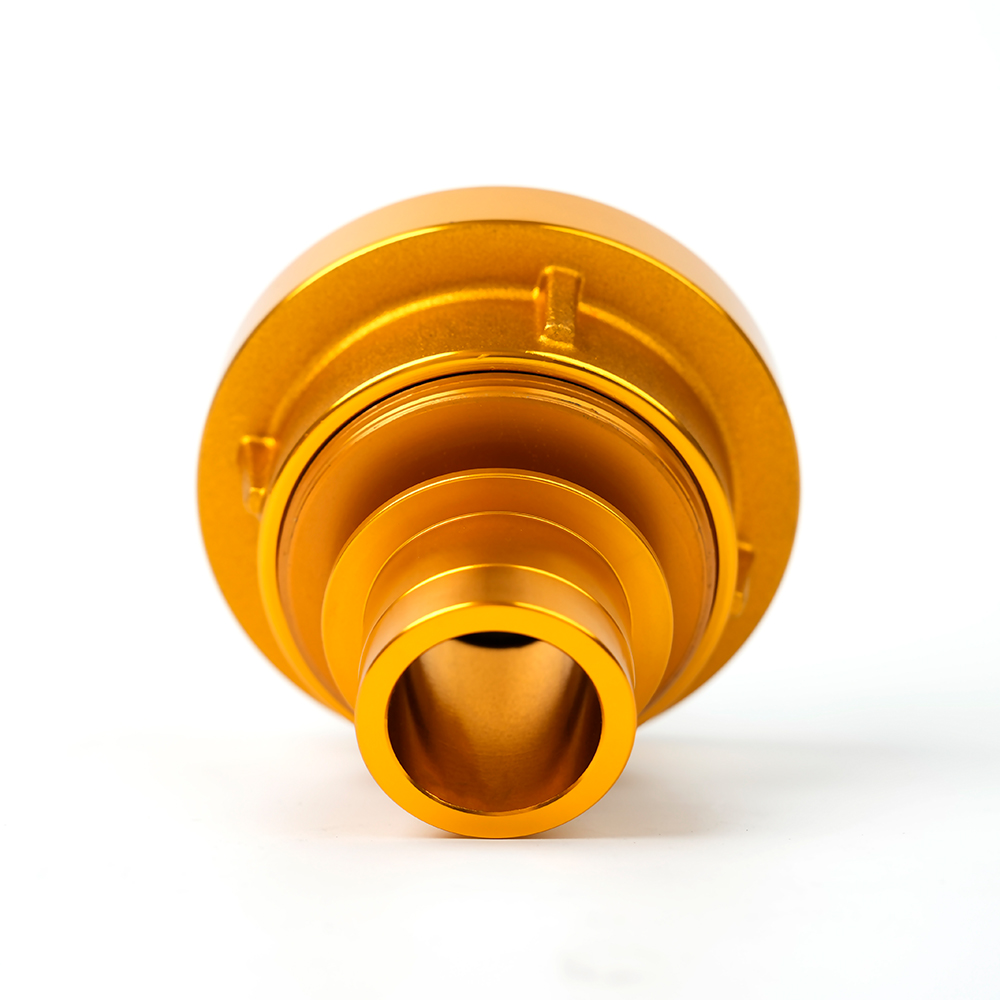 Storz Adapter Coupling with Male Machino ConnectionConnects Storz and male Machino interfaces, with multiple size combinations and customizable materials for cross-standard hydrant or hose setups.View Product →
Adapters cover the cross-standard case, for example when a municipal hydrant has to feed a hose set built to another standard, or when a plant buys equipment from two regions. A full range of cross-standard adapters covers combinations such as Storz to flanged, Storz to Machino, Storz to forestry and Machino to flanged, which is normally cheaper and faster than rebuilding outlets on site.
Most specifications call for counterclockwise to open, but direction is set by the standard and the local fire service and must match the marking on the operating nut. Confirm before delivery, then train on it.
On most dry barrel designs, yes. The bonnet comes off and the stem and seat are lifted out and replaced from the surface with the correct seat wrench. Wet barrel outlet valves are usually serviced the same way.
It follows from required flow and the outlet arrangement, not from habit. DN80 and DN100 cover most municipal hydrants, while industrial and refinery installations may need larger inlets and higher test pressures.
Sourcing the fire hydrant valve and the fittings around it from one manufacturer removes the mismatch risk behind most of these problems. Jiangsu Jinding Fire Protection Technology has produced fire hose couplings, adapters, blank caps, nozzles and distributors since 1998, holds ISO 9001:2015 certification and supplies test reports from the national fire equipment testing centre, with products built to Storz, Machino, NH, John Morris and Italian standards. If a specification is still open, send the outlet standards and pressure rating to the team and ask for a matched set rather than buying the valve and outlets separately.
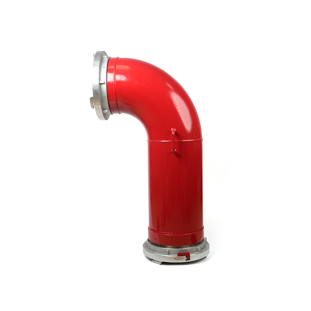 Grooved Fire Elbow-Storz
 Grooved Fire Elbow-Multi-tooth
 Multi-functional Fire Hose Distributor
 Locking Four-Way Fire Hose Distributor
 Locking Three-Way Fire Hose Distributor
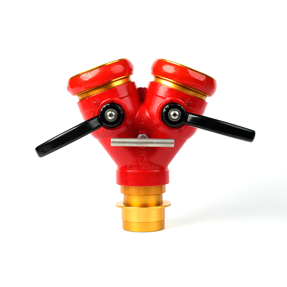 Locking Two-Way Fire Hose Distributor
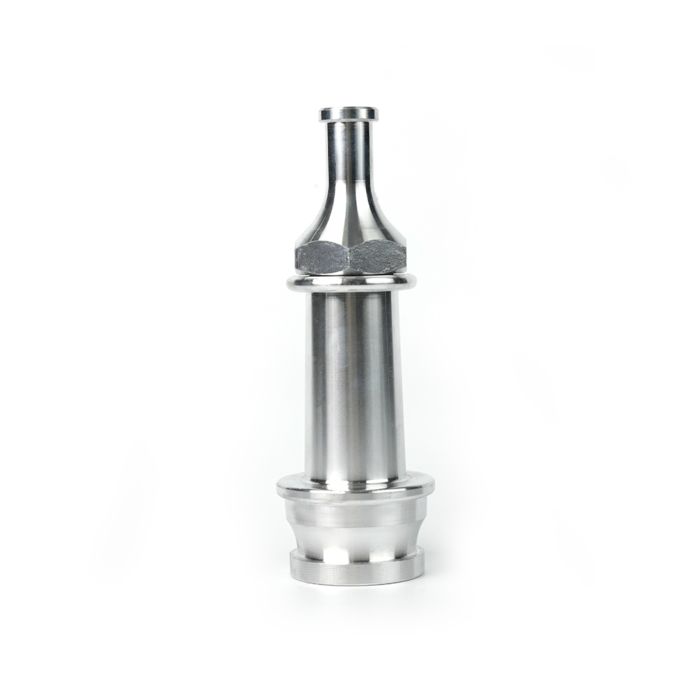 Straight Stream Nozzle
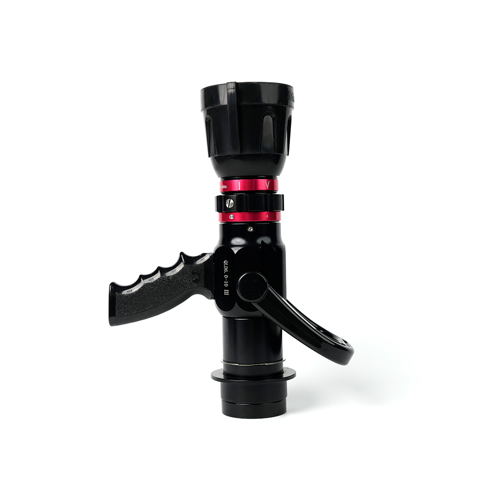 Adjustable nozzle-machino
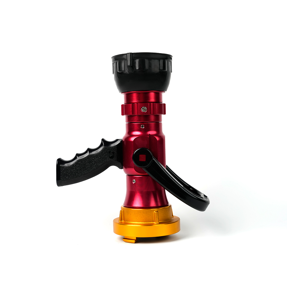 Adjustable nozzle-storz
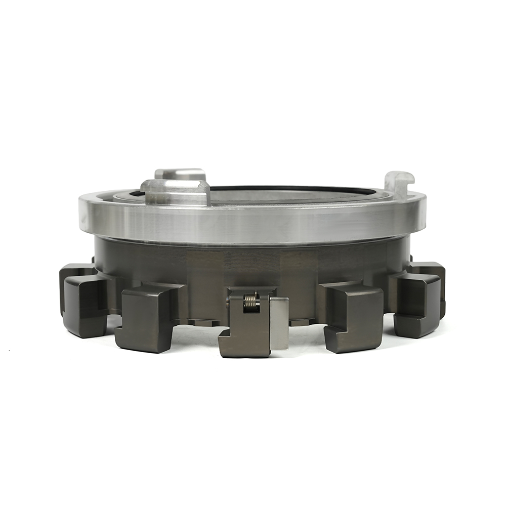 Storz Adapter Couplings - Multi-Tooth
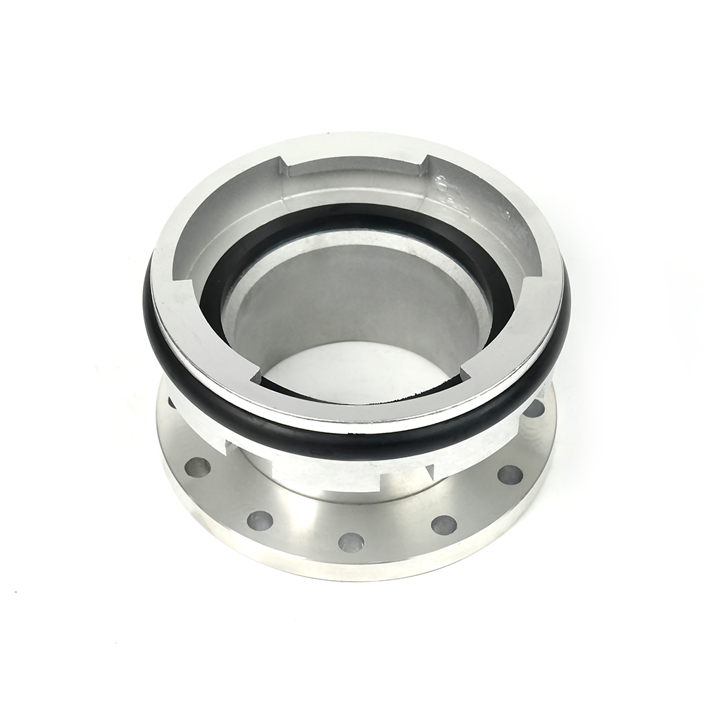 Machino Adapter Couplings – Flanged
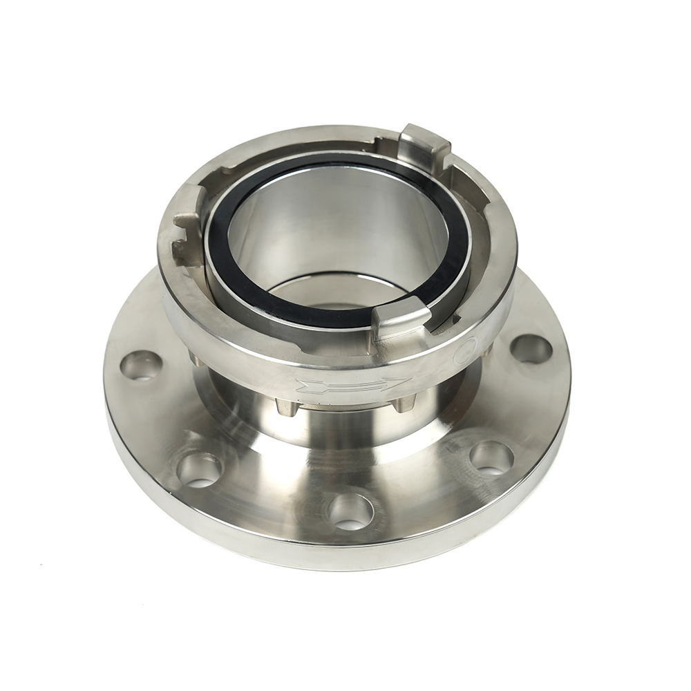 Storz Adapter Couplings – Flanged

 Contact Number
+86-0523-83274900
+86-151 9064 3365
 Let our team offer you customs solutions.
 Company Address
West side of Hongxing Middle Road, Lincheng Street, Development Zone, Xinghua City, Jiangsu Province, China
Copyright @Jiangsu Jinding Fire Protection Technology Co., Ltd. All rights reserved Fire Protection Equipments Manufacturers
