 英语
英语 西班牙语
西班牙语 德语
德语Industry News


GET IN TOUCH
+86-0523-83274900
+86-151 9064 3365
Content
Maintaining a straight stream nozzle properly requires a structured routine of post-use flushing, thorough inspection, lubrication of moving parts, correct storage, and scheduled functional testing — carried out after every deployment and at regular intervals between uses. A straight stream fire nozzle must be ready to deliver a dense, high-impact water column at full rated flow rate at a moment's notice; any degradation in its mechanical condition, sealing integrity, or flow passage cleanliness directly reduces its firefighting effectiveness and can create safety hazards for the operator during suppression operations.
Made from high-strength aluminum alloy or composite materials designed for durability in extreme conditions, straight stream nozzles are robust by design — but robustness does not mean maintenance-free. Sediment accumulation in the bore, corrosion at coupling interfaces, degraded O-ring seals, and stiff or inoperative ball valve switches are the most common failure modes, and all are preventable through consistent maintenance practice. The sections below cover every element of a complete straight stream nozzle maintenance program.
Flushing the nozzle with clean water immediately after every use is the single most impactful maintenance action available, and it takes less than two minutes. Fireground water supplies — hydrants, tankers, and natural sources — routinely carry sediment, mineral deposits, organic matter, and dissolved salts that are deposited inside the nozzle body and bore when water flow stops. If these deposits are allowed to dry and harden inside the nozzle, they reduce the effective bore diameter, disrupt stream formation, and can permanently score the bore surface over repeated cycles of contamination and drying.
If the nozzle was used on a fire involving foam concentrate, chemical suppression agents, or contaminated water sources, extend the flush time to a minimum of 3 to 5 minutes with clean water, and follow with an inspection of all internal surfaces for chemical residue before drying and storage. Foam concentrate residue in particular becomes highly adhesive when dried and can bond to aluminum surfaces, requiring mechanical cleaning if not removed immediately after use.
Post-flush visual inspection takes 5 to 10 minutes and identifies damage, wear, and developing problems while they are still minor and correctable. Nozzles returned to service with undetected damage are a safety risk — a nozzle that fails under operating pressure during a live fire event can injure the operator and leave a fire uncontrolled at a critical moment. Inspect every component systematically, working from the coupling end to the bore outlet.
The coupling interface is the highest-stress mechanical connection on the nozzle and the most common location for damage from rough handling, drops, and repeated connection and disconnection cycles. Examine the following:
The ball valve is a critical safety and operational component — it allows the firefighter to stop water flow instantly without signaling the pump operator, preventing pressure surges in the hose line and giving the operator control over water application. A stiff, sluggish, or non-returning valve is a operational hazard that must be corrected before the nozzle is returned to service.
The internal bore and stream former (the shaped exit orifice that forms the solid jet stream) are the hydraulic heart of a straight stream nozzle — their condition directly determines stream quality, range, and impact force. Inspect with a flashlight through both ends of the bore:
Examine the nozzle body for cracks, fractures, and impact damage — particularly at the coupling-to-body junction and around any threaded accessories or attachment points. Aluminum alloy bodies are highly impact-resistant but can crack if dropped from significant height onto hard surfaces or subjected to crushing loads in equipment compartments. Any crack in the nozzle body, however small, is cause for immediate removal from service — cracks propagate rapidly under operating pressure and can cause catastrophic body failure during use.
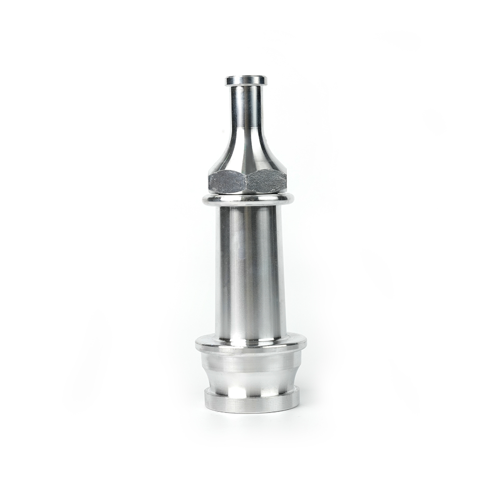
Deposits that are not removed by flushing alone require more active cleaning. The appropriate cleaning method depends on the type of deposit and the materials of the nozzle body — aluminum alloy requires different chemical handling than stainless steel or composite materials.
Calcium carbonate and other mineral scale deposits are best removed with a dilute acid solution. For aluminum alloy nozzles, use a solution of white vinegar (acetic acid, approximately 5% concentration) diluted 1:1 with water — this is mild enough to dissolve carbonate scale without attacking the aluminum substrate. Fill the nozzle bore with the vinegar solution, close the ball valve, and allow to soak for 15 to 30 minutes. Then flush thoroughly with clean water for at least 2 minutes to remove all acid residue.
Do not use stronger mineral acids (hydrochloric or phosphoric acid) on aluminum alloy nozzles without consulting the manufacturer's chemical compatibility guidance — these can attack the base metal and cause pitting that is worse than the original scale deposit. For stubborn scale that does not respond to soaking, use a soft nylon brush passed through the bore to mechanically assist the chemical dissolution. Never use steel wire brushes or abrasive tools on the bore surface.
Dried foam concentrate residue is tackier and more resistant to water flushing than mineral scale. Soak the affected areas in warm water (40°C to 50°C) with a small amount of mild dish detergent for 10 to 15 minutes, then flush with clean running water while working a soft brush through the bore. Warm water significantly accelerates the dissolution of dried foam concentrate compared to cold water flushing alone. After cleaning, flush with clean cold water for 2 minutes to remove all detergent residue before drying and storage.
The ball valve interior accumulates the same contaminants as the main bore but is harder to access for cleaning. Cycling the valve rapidly between open and closed positions during flushing — 10 to 15 cycles — creates turbulent flow that dislodges sediment from the ball surface and valve body. For more thorough cleaning of a persistently stiff valve, disassemble the valve following the manufacturer's instructions, clean the ball, valve seats, and body cavity individually with a soft cloth and mild cleaning solution, then reassemble with fresh lubrication on the ball and stem seals.
Proper lubrication of the ball valve and coupling seals is essential for smooth operation, watertight sealing, and long component life. An unlubricated ball valve on an aluminum alloy nozzle is susceptible to galling — a form of adhesive wear where metal-to-metal contact between the ball and valve seats transfers material from one surface to the other, causing roughness and ultimately seizure. Lubrication prevents this and also protects O-ring seals from drying and cracking, which is the most common cause of seal failure in stored equipment.
Use only lubricants that are:
Silicone grease in a tube or spray form is the universal recommendation for fire nozzle maintenance — it satisfies all the above requirements and is widely available. Apply a thin film to the ball valve stem where it exits the valve body, to the coupling gasket, and to any exposed O-rings accessible during routine maintenance. Do not over-lubricate — excess grease attracts sand and grit that becomes an abrasive compound on the valve surfaces.
Lubricate the ball valve stem and accessible seals after every use and at minimum every 3 months during periods of storage without use. Rubber O-rings stored dry without lubrication will develop surface micro-cracks (ozone cracking) within 6 to 12 months in typical storage environments, leading to seal failure at first pressurization. Quarterly application of silicone grease to all accessible seals prevents this and can extend seal service life from 2 to 3 years to 8 to 10 years.
O-rings and gaskets are the consumable sealing components of the nozzle — they will eventually require replacement regardless of maintenance quality, as rubber ages and loses elasticity over time. Knowing when to replace rather than re-lubricate is an important maintenance judgment call.
Replace O-rings and gaskets when any of the following conditions are observed:
Always use manufacturer-specified replacement O-rings and gaskets of the correct material grade, cross-section diameter, and internal diameter. Substituting O-rings from general hardware suppliers with the correct dimensions but wrong material specification is a common maintenance error — a Nitrile O-ring installed in an application designed for EPDM may swell and jam the ball valve, while a non-fire-rated material may fail from heat exposure near a fire. Maintain a stock of the correct replacement seal kit for every nozzle model in service.
Visual inspection and lubrication cannot substitute for pressure testing — the only definitive verification that a nozzle will maintain a leak-free, fully functional condition under the operating pressures it will encounter in service. Pressure testing should be performed after any repair, after any incident involving suspected mechanical damage, and at intervals not exceeding 12 months as part of scheduled equipment certification.
Any leakage at working pressure or test pressure is a failure — identify the source, repair or replace the relevant component, and retest before returning the nozzle to service. Record all test results in the equipment maintenance log with the date, test pressure, and pass/fail result.
In addition to hydrostatic testing, a periodic flow test verifies that the nozzle delivers the rated flow rate and stream quality. Connect to a metered water supply, open the ball valve fully at rated inlet pressure, and measure flow rate with a calibrated flow meter or by timed volume collection. Flow rate should be within ±5% of the manufacturer's rated capacity at the specified inlet pressure — typically 7 bar (100 psi) for standard firefighting nozzles. Reduced flow rate indicates bore obstruction, scale buildup, or incorrect test pressure. Observe the solid stream for coherence, straightness, and range — a broken, twisted, or shortened stream indicates bore surface damage or stream former damage that requires investigation.
High-strength aluminum alloy provides an excellent combination of light weight and corrosion resistance, but aluminum is not immune to corrosion — particularly galvanic corrosion that occurs when aluminum contacts dissimilar metals in the presence of water, and crevice corrosion that develops in tight-fitting joints where water becomes trapped. Both are preventable with correct maintenance and material selection awareness.
Galvanic corrosion occurs when aluminum nozzle couplings are connected to brass or stainless steel hose couplings in the presence of water — the electrochemical potential difference between the metals causes preferential corrosion of the less noble metal (aluminum). Symptoms include white powdery deposits around the coupling thread area and progressive pitting of the thread form. Preventive measures include:
Aluminum naturally forms a protective oxide layer that limits further corrosion in most environments, but this layer is disrupted by mechanical abrasion (such as rough storage contact), chemical exposure (chlorinated water or foam concentrate), and salt spray in coastal environments. Wipe external nozzle surfaces with a clean, lightly oiled cloth after cleaning and before storage to restore a thin protective oil film. For nozzles used in coastal or high-humidity environments, a light application of corrosion-inhibiting spray to all external surfaces after each use provides additional protection.
A significant proportion of nozzle maintenance problems originate during storage rather than during use. Stiff ball valves, cracked O-rings, and corroded couplings are frequently the result of inadequate storage conditions rather than service wear. Correct storage preserves the nozzle in ready-to-deploy condition for the full period between uses — whether that is overnight on an appliance or months in reserve stock.
The following table consolidates the complete straight stream nozzle maintenance program into a single reference schedule organized by frequency, with estimated time requirements and responsible party guidance:
| Frequency | Maintenance Task | Est. Time | Responsible |
|---|---|---|---|
| After every use | Flush with clean water (min. 60 sec); visual inspection of coupling, valve, and bore; ball valve lubrication; dry and store correctly | 10–15 min | Assigned firefighter / crew |
| Weekly (apparatus check) | Confirm coupling protectors in place; check ball valve moves freely; verify storage position is half-open | 2–3 min per nozzle | Apparatus check crew |
| Monthly | Full visual inspection of all components; O-ring condition check; re-lubricate ball valve stem and coupling gasket; inspect for corrosion | 15–20 min | Equipment officer / technician |
| Quarterly | Deep clean bore and valve; descale if required; replace O-rings and gaskets showing any deterioration; apply corrosion protection to external surfaces | 30–45 min | Equipment officer / workshop |
| Annually | Hydrostatic pressure test to 1.5× working pressure; flow rate and stream quality test; full O-ring replacement regardless of condition; complete inspection report | 45–60 min | Qualified equipment technician |
| After any suspected damage | Full inspection + hydrostatic test before return to service; remove from service immediately if damage confirmed; document incident and repair | As required | Equipment officer / workshop |
The following table summarizes the most frequently encountered maintenance problems on straight stream nozzles, their most probable root causes, and the corrective actions required to restore correct function:
| Problem | Probable Cause | Corrective Action |
|---|---|---|
| Stiff or seized ball valve | Dried deposits on ball surface; missing lubrication; corrosion of stem; damaged valve seats | Soak in warm water and cycle valve; disassemble, clean, and lubricate; replace seats if worn |
| Leakage through closed ball valve | Worn or damaged valve seats; grit or debris on ball seating surface; incorrect valve closure | Clean ball and seats; replace seats; confirm valve is fully closed; replace ball assembly if seats are scored |
| Leakage at coupling connection | Damaged or compressed coupling gasket; damaged thread; incorrect coupling engagement | Replace coupling gasket; inspect threads; ensure coupling is fully engaged before pressurizing |
| Reduced flow rate below rated capacity | Mineral scale in bore; foreign object obstruction; partially open ball valve; inadequate inlet pressure | Descale bore; remove obstruction; verify valve is fully open; check inlet pressure at specified test conditions |
| Broken or twisted stream at outlet | Damaged stream former orifice; bore surface scoring; partial bore obstruction; bore scale | Inspect and clean bore; remove obstruction; if stream former is damaged, replace nozzle tip or complete nozzle |
| White deposits on coupling threads | Galvanic corrosion from dissimilar metal coupling contact; mineral scale from standing water | Clean with dilute vinegar solution; apply anti-seize or silicone grease to threads; disconnect after use; consider coupling compatibility |
| Coupling swivel stiff or seized | Corrosion in swivel bearing race; sediment accumulation; impact damage to swivel ring | Clean and lubricate swivel bearing; if impact-damaged, assess whether deformation affects coupling engagement; replace if seized |
| O-ring failure / leakage at body joints | Age hardening or cracking of O-rings; incorrect O-ring material; O-ring omitted during prior reassembly | Replace all O-rings at affected joint with correct grade; do not reuse O-rings removed during disassembly; verify correct material specification |
A consistently maintained straight stream nozzle is a reliable, high-performance tool that should deliver years of trouble-free service across its rated operating conditions. The small investment of time required for post-use flushing, regular inspection, lubrication, and annual testing is measured in minutes per event — far less than the time and resources required to manage nozzle failures during active firefighting operations, or the consequences of equipment unavailability when a nozzle fails a pre-incident inspection at the moment it is most needed.
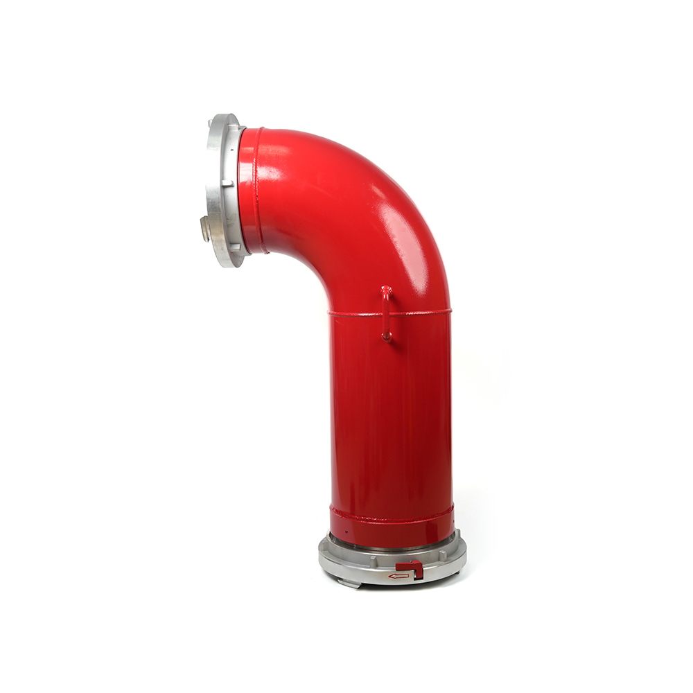 Grooved Fire Elbow-Storz
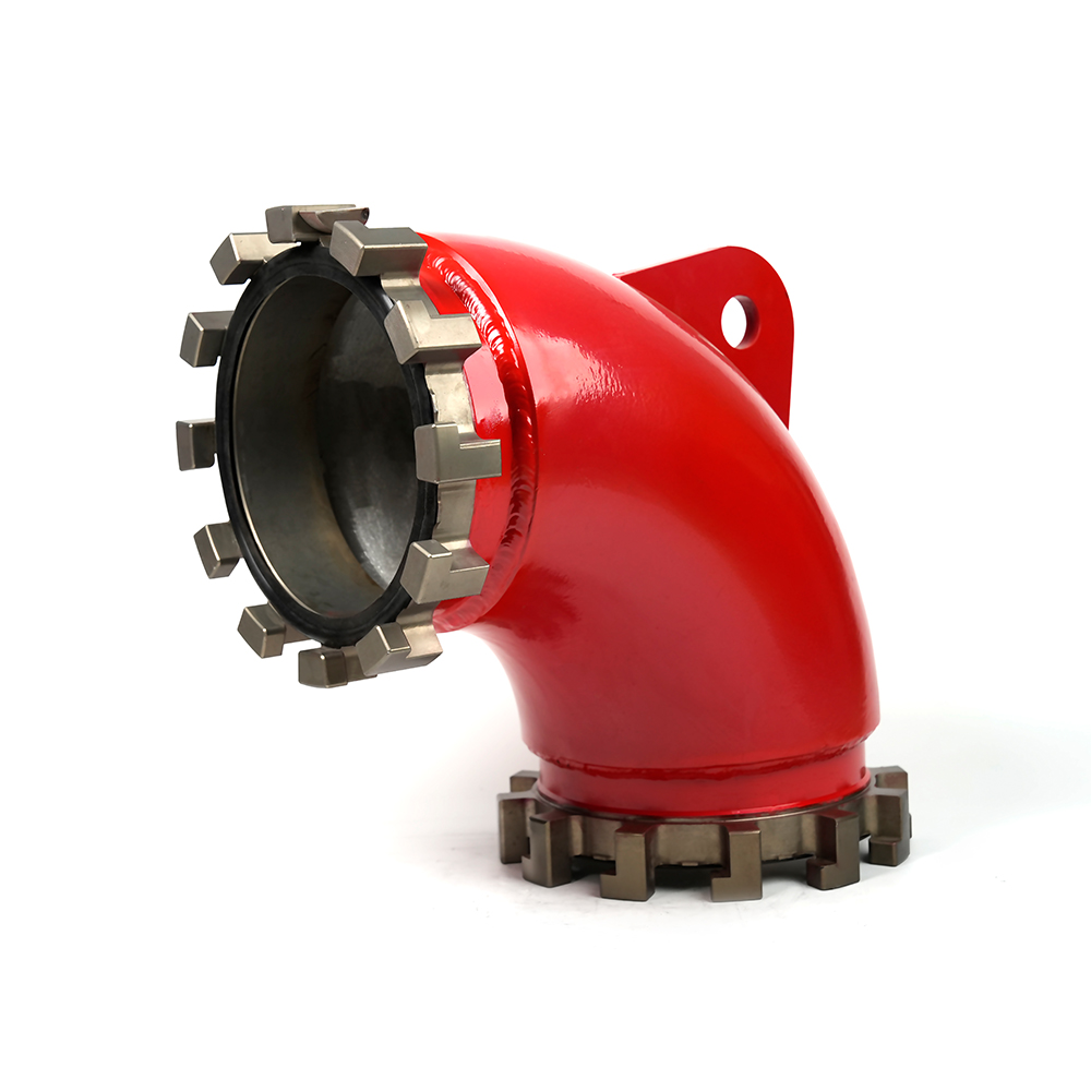 Grooved Fire Elbow-Multi-tooth
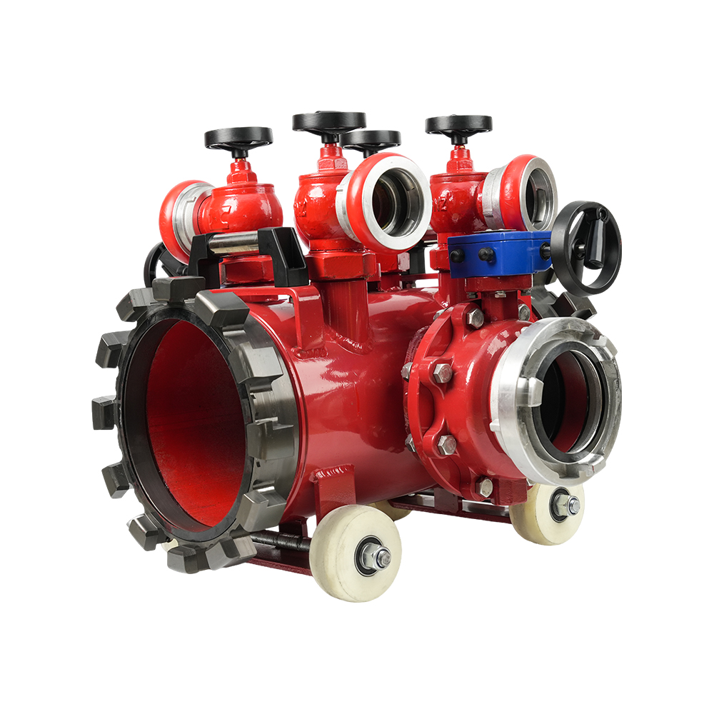 Multi-functional Fire Hose Distributor
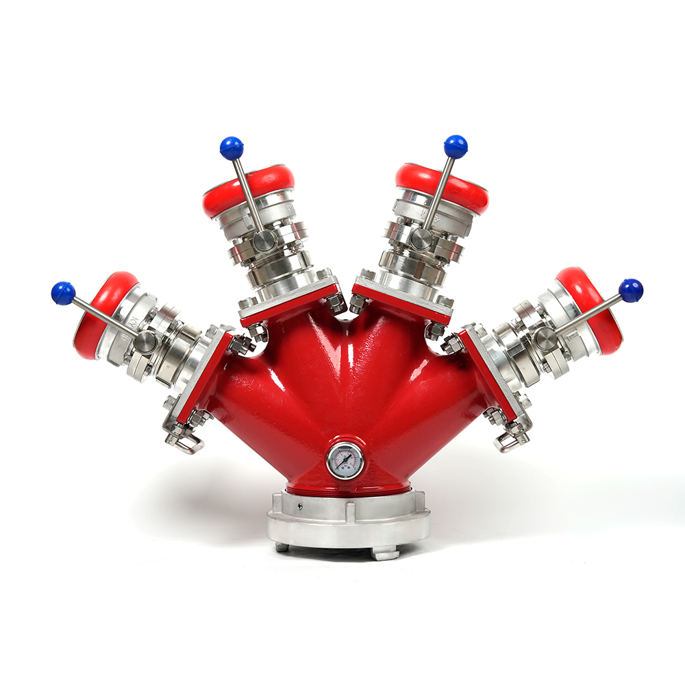 Locking Four-Way Fire Hose Distributor
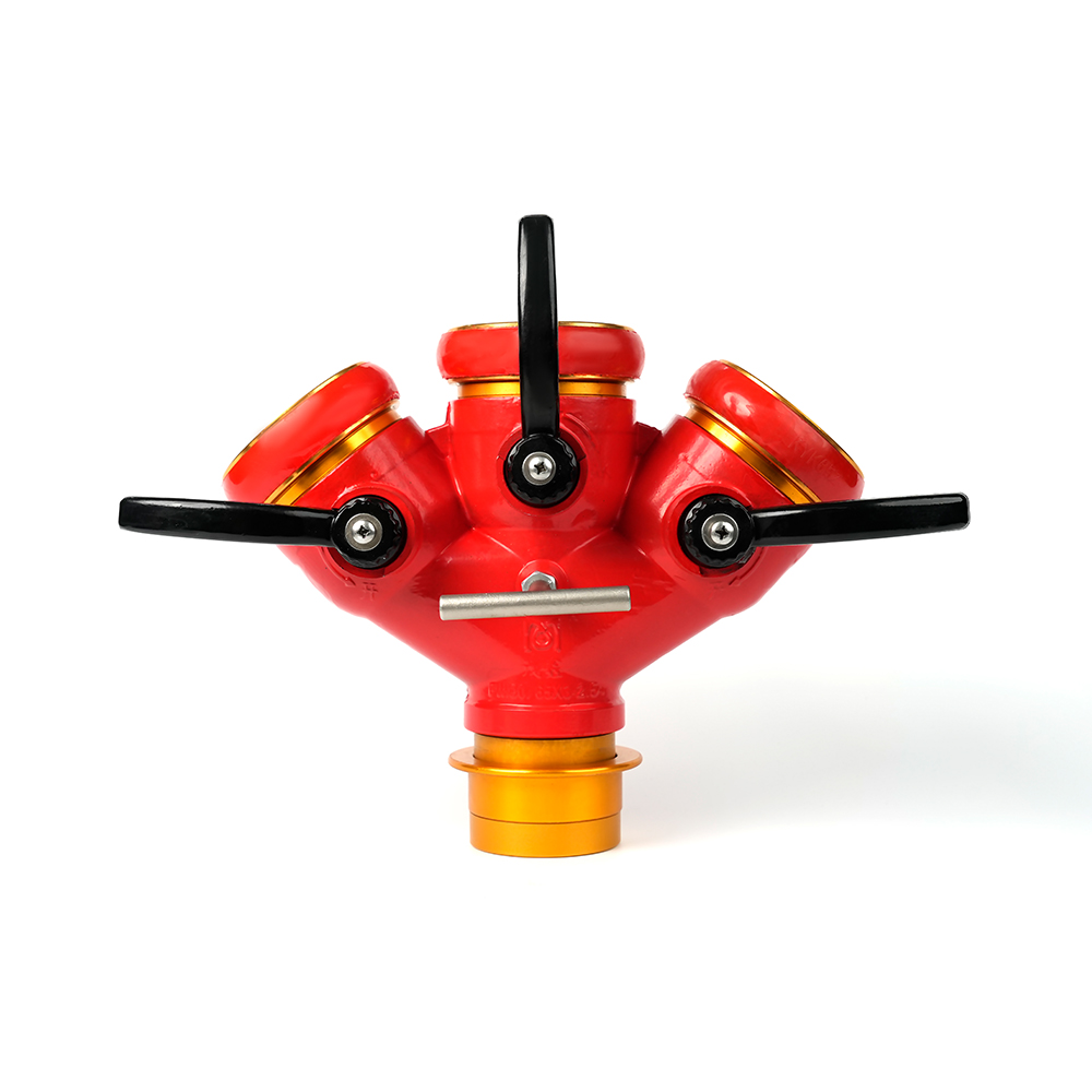 Locking Three-Way Fire Hose Distributor
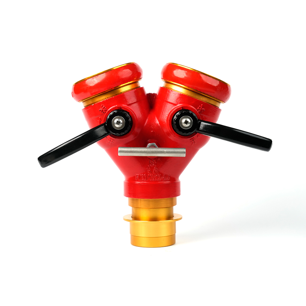 Locking Two-Way Fire Hose Distributor
 Straight Stream Nozzle
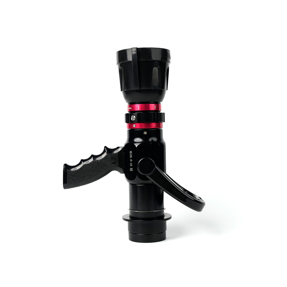 Adjustable nozzle-machino
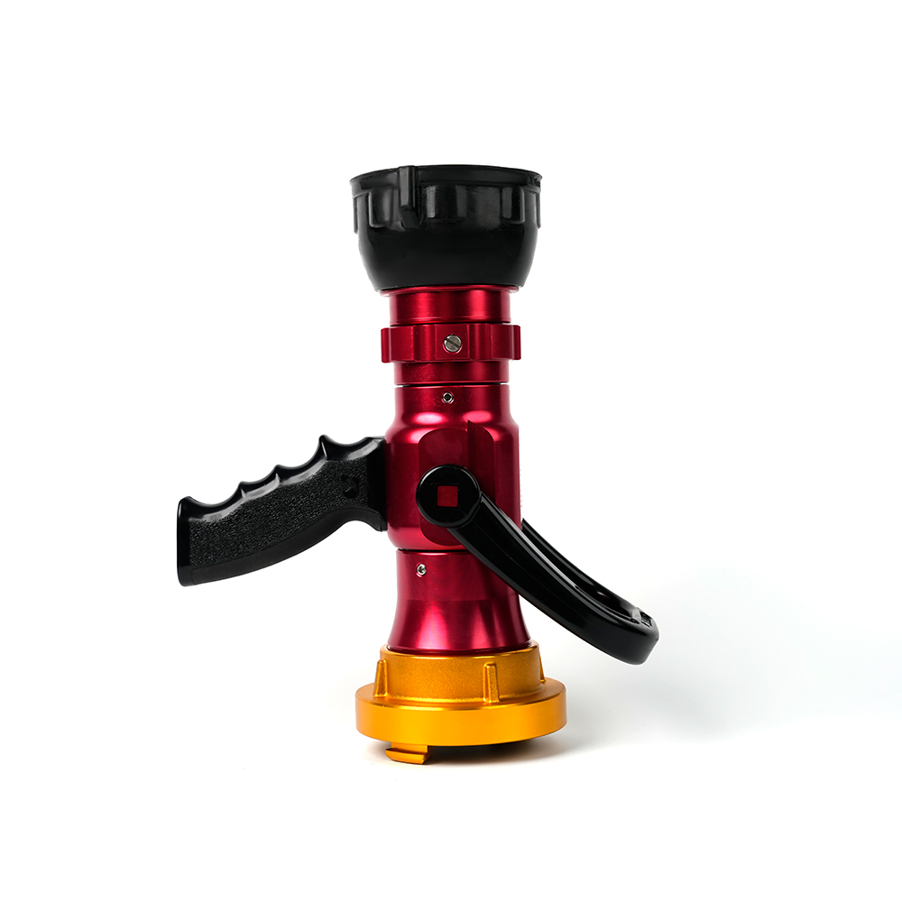 Adjustable nozzle-storz
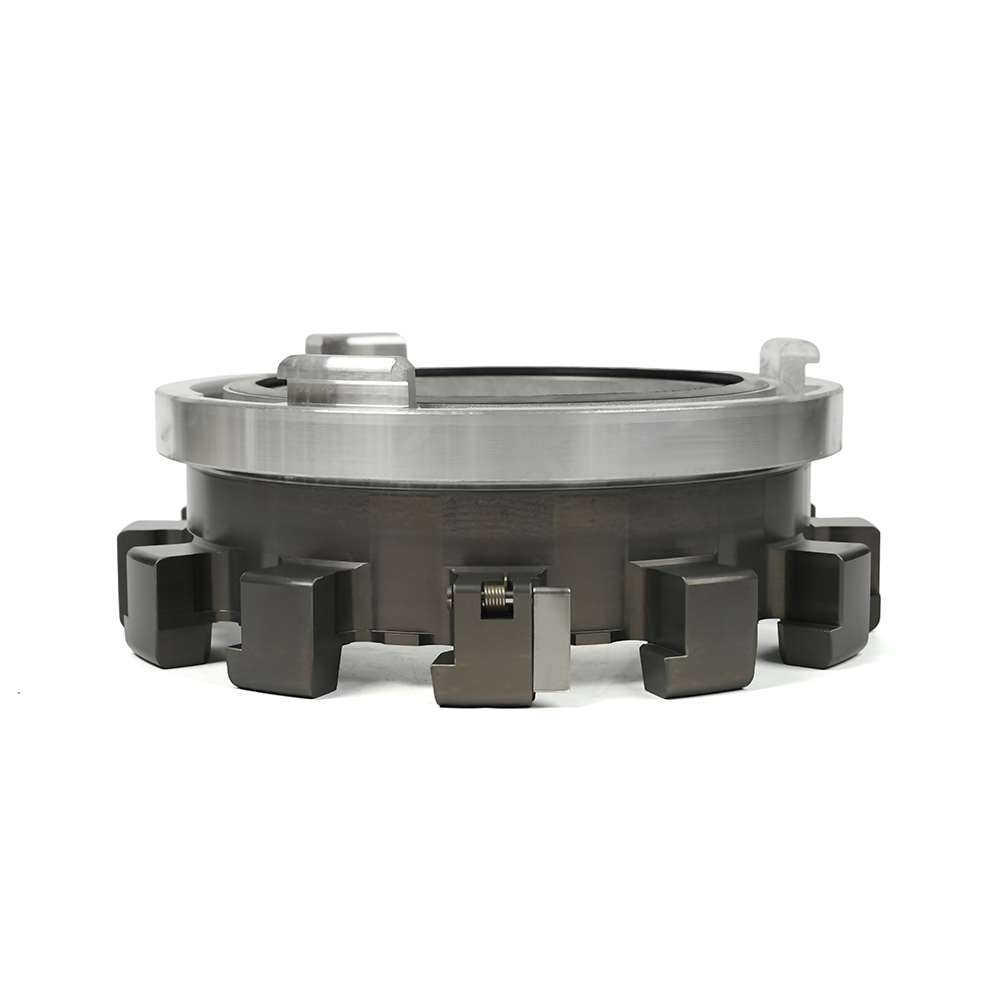 Storz Adapter Couplings - Multi-Tooth
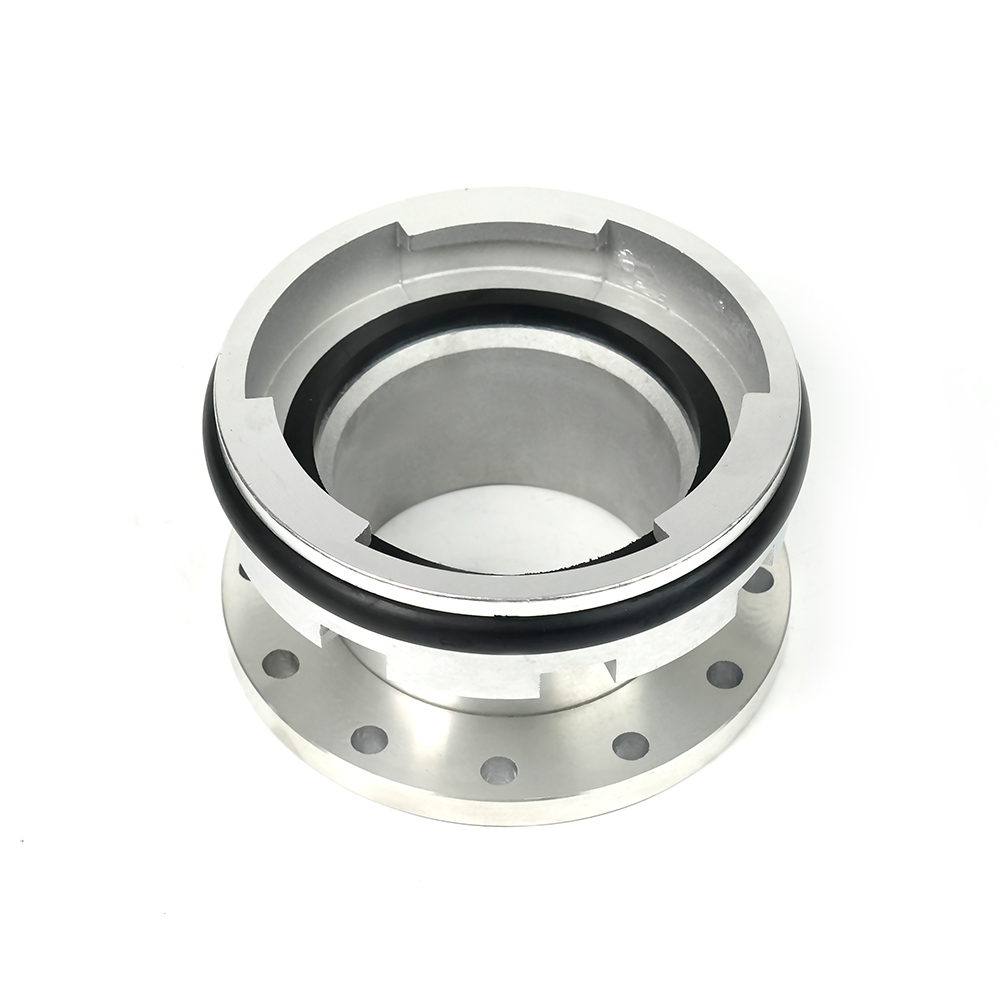 Machino Adapter Couplings – Flanged
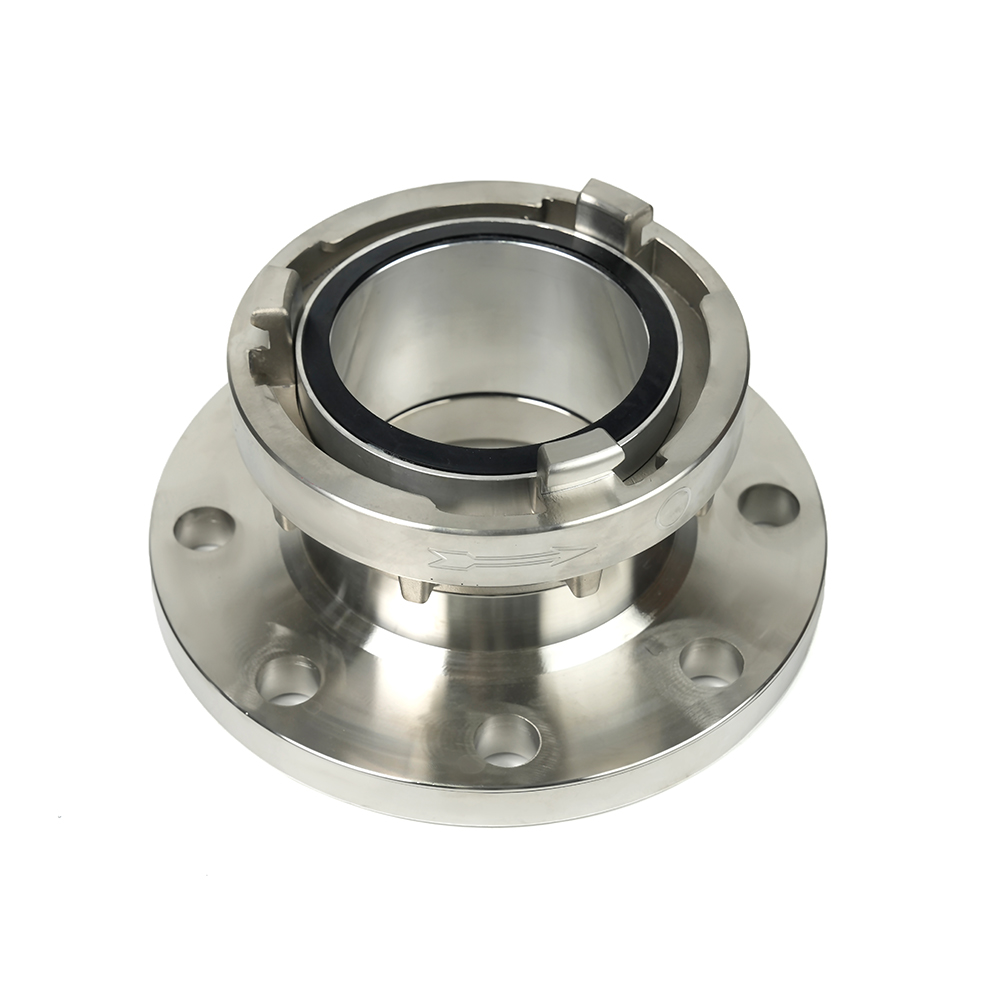 Storz Adapter Couplings – Flanged

 Contact Number
+86-0523-83274900
+86-151 9064 3365
 Let our team offer you customs solutions.
 Company Address
West side of Hongxing Middle Road, Lincheng Street, Development Zone, Xinghua City, Jiangsu Province, China
Copyright @Jiangsu Jinding Fire Protection Technology Co., Ltd. All rights reserved Fire Protection Equipments Manufacturers
